J Pole Colinear
I operate mainly on HF and VHF from a relatively
exposed site on the North coast of Northern Ireland. I wanted a simple
no-nonsense antenna that was cheap, quick and easy to build and robust enough to
stand up to the local weather conditions. Of course, I could have bought
something, but using copper pipe from the local plumbing supermarket and simple
components, I built an effective antenna that gives me 8dB gain and so far has
stood up to the Atlantic gales. And all for around £20! If you fancy trying
something similar, here’s how I did it.
Here’s what you need:
|
3 Meters 15 mm diameter copper pipe (as used in pluming)
14No. 90o bends solder type (Yorkshire)
Solder (lead free)
Blow torch
Small pieces Perspex 50 mm x50 mm
UHF SWR Bridge
Uhf transceiver 430 –440 MHZ
8No. 3mm diameter 25 –35 mm long bolts and nuts and washers
Pipe cutter or hacksaw |
Use
a pipe cutter (you can get a small hand-held one for a few pounds) to cut the
copper pipe into:
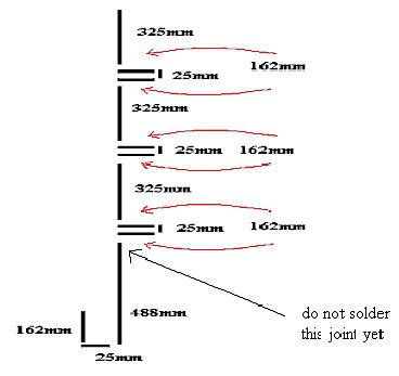
1
piece 488mm
7
pieces 162mm
4
pieces 25mm
3
pieces 325mm
It
is important to get the measurements accurate to the nearest millimetre as this
affects the performance. Put the sections together as shown in the diagram
below. I put mine together on the garage floor and used a blow lamp to join them
with Yorkshire (pre-soldered) connectors. Make
sure the rods are pushed well down into the right angle bends before you solder
them. Do not solder the bottom joint yet, as you need to fix the termination
first and it’s easier to handle a smaller assembly. And a personal word of
advice- make sure that it is cool before you pick it up!
To
make the U-bend at the bottom I used two 900 Yorkshire bends joined
together with one of the 25mm pieces of pipe.

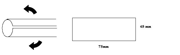
Next,
I made the termination to the N socket. To do this I cut a piece of Perspex 35mm
wide by 35mm height and mounted the N socket on to the Perspex. Note that the
N-plug is mounted asymmetrically; the reason for this will become apparent
later. I recommend using an N plug rather than a PL259 as they are designed for
UHF and give better performance. If you use PL259 plugs at UHF you may find that
it doesn’t give constant termination impedance. This is due to their construction. These changes in impedance
cause small changes in Standing Wave Ratio (SWR) and they produce some miss
match and loss.

From
the pieces of pipe left, I cut two pieces approximately 75 mm long and cut along
the length of each piece. Then I opened and flattened the tube to make 2 flat
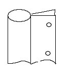
copper sheets. This copper strip wraps around the lower section of each element
as shown in the diagram, leaving both ends to attach to the Perspex. The strip
on the driven (longer) element should be in contact with the casing of the N
plug, but the other strip should be clear of it. To secure the assembly I
drilled holes to match those in the N plug and Perspex through both ends of the
copper strip on the driven side and bolted the strip on the non-driven side
directly to the Perspex.
The
case on the N Plug is the earth and this goes to the short (162mm) element of
the J pole and the centre pin of the N plug goes to the longer (498 mm) element.
Once this assembly was in place, I was able to solder the final joint on the
long element. Complete the assembly by closing off the ends of the pipe: stop
ends, pieces of dowel or even corks will do.

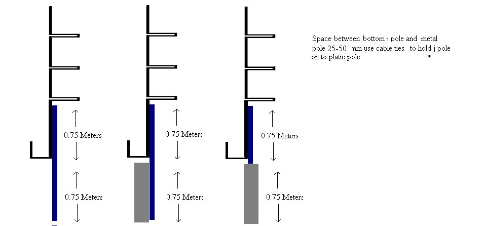
Finally,
I attached the complete assembly to a rigid plastic tube, at least ¾ metre
long, using either strong cable ties or Jubilee Clips. It is important to use
non-conducting material for the support and to ensure that it long enough to
both stabilise the long element and make a secure connection to the mast.
Setup
To
set up the antenna, I mounted the co-linear on a temporary pole approximately 6
–10 feet high (I used the washing line pole, but don’t tell the wife) and
connected the SWR bridge to the antenna. I used my home-made UHF SWR bridge.
I connected the SWR bridge to the transceiver (mine is a FT847)
and set the frequency to 434
Mhz., around the middle of the UHF band. I used Westflex H103; H100 would also
do, but if you use RG213 it should be as short as possible as with UHF the cable
losses are greater. With the power set to 5w I transmitted a UHF carrier and
checked SWR, moving the termination carriage up and down to produce the best
(minimum) SWR. If the initial SWR is >2.5
do not transmit for long periods of time as the high SWR could damage the
transceiver. Once the SWR was OK, I
put two bolts through the termination carriage and the elements of the J pole to
secure the termination.
Once
everything was working properly I mounted the antenna assembly on a 15 metre
section thick walled aluminium mast, secured by six guys. You will need to find
your own way of doing this to suit your local conditions and available space.
Reconnect the transceiver…. and away you go.
I
have been using the antenna for six months and can regularly access UHF
repeaters in Ballycastle (20km) and Londonderry (80km), the latter giving a very
good signal.
Taking
it further
The
same basic design can be used for other bands, changing the dimensions
appropriately. I have used the basic J-Pole design for 4metre band, which I use
for my echo link operating on 70.35 Mhz and for 2 metres which is working well
and can connect with the Donegal repeater 100km away.
Recently
I have been constructing a VHF antenna for a friend using a similar design, but
with 22mm pipe to give the extra rigidity required for an antenna of this
length.

M0RTX J-pole co-linear installed at Dervock, Co Antrim
![]()
![]()