| When feeding or receiving the signal from more than one antenna, it is necessary to split/combine the signal whilst maintaining the correct impedance. The following text and examples will hopefully help in the design of a splitter/combiner to meet your needs. On my software page there are programs available to calculate tube and co-ax sizes. |
|
Design considerations |
| The characteristic feedline impedance must be matched by the splitter/combiner to the impedance of the antenna feedlines. The best way to do this is to use a quarter wavelength transmission line of the correct impedance which can be calculated from the following formula: |
|
 |
|
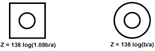
| The normal method of construction at VHF (due to physical size) is with Co-Axial cable, at UHF and above, it is more common to use round or square outer section with a round inner and air as the dialectric, although Co-Axial cable can still be used sucessfully. |
|
Impedance Calculation |
| The characteristic impedance of the round and square outer section lines can be found from the following formula: |
|
 |
 |
|
|
Build Considerations |
| Although these formula are not accurate for low impedances, they are quite satisfactory for normal feed line use. Further inaccuracies will be introduced during construction by having to use the nearest available centre conductor tube size, the length of the pins on the N connectors and build inaccuracies. All of these will cause the required centre frequency to 'move' slightly, the effect will be more pronounced the higher the frequency. For this reason it is most important to be as accurate as possible during construction. |
|
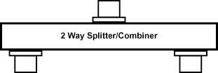
2 Way Splitter/Combiner |
|
 |
|
| As an example, we will assume that the splitter will be connected to 2 antenna each of 50 ohm impedance, they must each be connected by a quarter wave line to the centre N connector. At the centre connector an impedance of 100 ohms on each quarter wave line will be required to match the 50 ohm feed line (100 +100 in parrallel = 50). To determine the required quarter wave impedance we can use the formula: |
|
 |
|
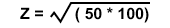
| Z1 = 50 ohm (antenna impedance), Z2 = 100 ohm (quarter wave line impedance) |
|
 |
 |
 |
|
| For a feedline impedance of 50 ohms this will always be the required impedance for the quarter wave line irrespective of frequency. |
|
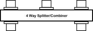
4 Way Splitter/Combiner |
|
 |
|
| As an example, we will assume that the splitter will be connected to 4 antenna each of 50 ohm impedance, they must be connected by a quarter wave line to the centre N connector. At the centre connector an impedance of 100 ohms on each quarter wave line will be required to match the 50 ohm feed line (100 +100 in parrallel = 50). As in the 2 Way splitter we can use the same formula to determine the required quarter wave impedance we can use the formula: |
|
|
|
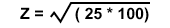
| However, this time Z1 = 25 ohm (2 x 50 antenna impedance in parallel), Z2 = 100 ohm (quarter wave line impedance) |
|
 |
 |
 |
|
| For a feedline impedance of 50 ohms this will always be the required impedance for the quarter wave line irrespective of frequency. |