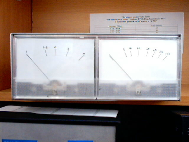
SWR & Power Meter
The circuit uses a current transformer
in which the low resistance of the 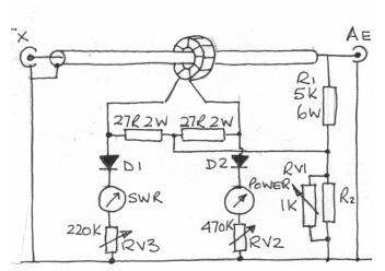 secondary
is split into two equal parts. The centre connection is taken
to the voltage sampling network so that the sum and difference
voltages are available at the ends of the transformer secondary
windings. The layout of the sampling circuit is important: the
input and output sockets should be only a few inches apart and
connected together with a short length of coaxial cable, as shown
in the picture. The coaxial outer must be earthed at
one end only so that it acts as an electrostatic screen between
the primary and secondary windings of the torroidal transformer. The
primary of the torroidal transformer is formed by simply threading
a ferrite ring onto the coaxial cable. 12 turns of
24 swg enamelled copper wire equally spaced around
secondary
is split into two equal parts. The centre connection is taken
to the voltage sampling network so that the sum and difference
voltages are available at the ends of the transformer secondary
windings. The layout of the sampling circuit is important: the
input and output sockets should be only a few inches apart and
connected together with a short length of coaxial cable, as shown
in the picture. The coaxial outer must be earthed at
one end only so that it acts as an electrostatic screen between
the primary and secondary windings of the torroidal transformer. The
primary of the torroidal transformer is formed by simply threading
a ferrite ring onto the coaxial cable. 12 turns of
24 swg enamelled copper wire equally spaced around 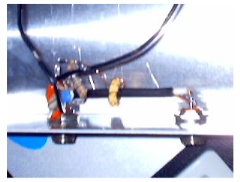 the
entire circumference of the ring form the secondary winding. The
ferrite material should maintain a high permeability throughout
the frequency range up to 70Mhz; a suitable ferrite ring is the
MullardFX1596. Other components in the sampling circuit
should have the shortest possible leads. R1 and R2
should be non inductive types. For powers above about 100W R1
should be several 2W carbon resistors in parallel. R2 should
be 150 ohms for 75 ohms systems and 220 ohms for 50 ohm systems.
RV1 should be a miniature skeleton preset soldered directly
across R2 to keep any stray reactance to a minimum. The
detector diodes D1 and D2 should be matched point contact types
with a PIV rating of about 50v, OA79 and OA91 are suitable. The
27 ohm 2W current transformer resistors should be matched to 5%.
The ratio of the sampling resistors R1 and R2 is determined by
the sensitivity of the current sensing circuit. The two sampling
voltages must be equal in magnitude under matched conditions,
and RV1 provides a fine adjustment of the ratio. The two
meters are moving coil 50µA FSD and RV2 and RV3 are miniature
skeleton presets soldered directly to their respective meters.
the
entire circumference of the ring form the secondary winding. The
ferrite material should maintain a high permeability throughout
the frequency range up to 70Mhz; a suitable ferrite ring is the
MullardFX1596. Other components in the sampling circuit
should have the shortest possible leads. R1 and R2
should be non inductive types. For powers above about 100W R1
should be several 2W carbon resistors in parallel. R2 should
be 150 ohms for 75 ohms systems and 220 ohms for 50 ohm systems.
RV1 should be a miniature skeleton preset soldered directly
across R2 to keep any stray reactance to a minimum. The
detector diodes D1 and D2 should be matched point contact types
with a PIV rating of about 50v, OA79 and OA91 are suitable. The
27 ohm 2W current transformer resistors should be matched to 5%.
The ratio of the sampling resistors R1 and R2 is determined by
the sensitivity of the current sensing circuit. The two sampling
voltages must be equal in magnitude under matched conditions,
and RV1 provides a fine adjustment of the ratio. The two
meters are moving coil 50µA FSD and RV2 and RV3 are miniature
skeleton presets soldered directly to their respective meters.
SWR/Power Meter Calibration
Accurate calibration requires an
RF voltmeter and a tapped dummy load, but adequate calibration
can be achieved with the transmitter's built-in power meter. Connect
the transmitter to the connector at the opposite end of the coaxial
line from the voltage sampling network, and connect a dummy load
of the correct impedance to the other connector. Switch
on the transmitter and adjust it's power output to 100 watts,
(or until the voltage across the dummy load equates to 100 watts).
Adjust RV1 for minimum reflected power indication. Calibrate
the forward power meter first by adjusting RV2 to give full scale
deflection on the forward power meter with the transmitter power
output set to 100 watts. Then reduce the transmitter power
output in 20 watt steps, marking the forward power meter scale
accordingly. The forward power meter scale can then
be marked permanently in watts. To calibrate the reflected
power meter for direct SWR reading, switch off the transmitter
and reverse the transmitter and dummy load connections, ie, connect
the transmitter to the sampling end and the dummy load to the
other end. Switch the transmitter back on, set it's power output
to 100 watts and adjust RV3 for full scale deflection on the reflected
power meter. SWRs of 1.5, 2 and 3 correspond to reflected
powers of 4%, 11% and 25% respectively, which for a forward power
of 100 wa tts
correspond to 4 watts, 11 watts and 25 respectively. Therefore,
to calibrate the reflected power meter directly in SWR simply
reduce the transmitter power to 25 watts and mark the reflected
power scale for a SWR of 3, reduce the transmitter power to 11
watts and mark the scale for a SWR of 2, reduce the power to 4
watts and mark the scale for a SWR of 1.5. For completeness,
the meter pointer can be marked for a SWR of 1, (ie no reflected
power) at its rest position and } at FSD
for a SWR of disaster. Calibration is now complete and the
meter will read simultaneous direct readings of forward power
and associated SWR.
tts
correspond to 4 watts, 11 watts and 25 respectively. Therefore,
to calibrate the reflected power meter directly in SWR simply
reduce the transmitter power to 25 watts and mark the reflected
power scale for a SWR of 3, reduce the transmitter power to 11
watts and mark the scale for a SWR of 2, reduce the power to 4
watts and mark the scale for a SWR of 1.5. For completeness,
the meter pointer can be marked for a SWR of 1, (ie no reflected
power) at its rest position and } at FSD
for a SWR of disaster. Calibration is now complete and the
meter will read simultaneous direct readings of forward power
and associated SWR.