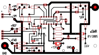
This PCB (103x58 mm) is made with ABACOM software SPrintLayout 3.0, thats why it is in .lay-format. For a perfect reading and printing all its data and contents, use the Abacom's free ware SPrint-Layout 4.0 - Viewer (about 1.1 MB).
Bellow is the brand-new, rewrited from me design of the world famous scheme. For perfect reading and printing from its original .pcb-format use the Abacom's free ware SPlan 6.0 - Viewer (about 1.7 MB).
The original design (scheme & PCB) you can find too at Dominique's - F1FRV publication - AUTOMATIC SWR METER AND TUNING UNIT. (Revision 3: June 2006)
F1FRV's scheme version with single power supply is a lot better
(more applicable, rational) than the DD2JI's dual supplies.
Another good idea is the replacement of the common diode with a zener
(better temperature stability), as well the increased reference voltage.
Another good source for the DD2JI's original scheme you can find at UN7GM's publication in russian: Автоматический КСВ-метр
The original work by Harald Pietzko, DD2JI in German (96 kB in DjVu - scanned and converted by Igor, UN7GM) you can downloaded from the renowned Russian radioamateur server SKR: //www.cqham.ru.
NOTICE.
For power measuring (at 50 ohm dummy load) I had supplement switch and trimmer potentiometer, at +FWD-input, like it is shown below.
As well in my PCB at the solder side are foreseed two landings (soldering footprints) for SMD's SOT323 (MOS-FETs 2N7002, instead of 2N7000).
My full description of this aSWR&PWR meter (including measure head & construction) will be come sooner (or later :)).
lz1len / Apr. 2007 / eof
 Back to my projects page