|
Null Modem Cable
The purpose of a null-modem cable is to permit two RS-232
"DTE" devices to communicate with each other without modems or
other communication devices (i.e., "DCE"s) between them.
To achieve this, the most obvious connection is that the
TD signal of one device must be connected to the RD input of the other
device (and vice versa).
Also, however, many DTE devices use other RS-232 pins for
out-of-band (i.e., "hardware") flow control. One of the
most common schemes is for the DTE (the PC) to assert the RTS signal if it
is ready to receive data (yes, it DOES sound backwards, but that's how it
works), and for the DCE (the modem) to assert CTS when it is able to
accept data. By connecting the RTS pin of one DTE to the CTS pin of
the other DTE, we can simulate this handshake.
Also, it is common convention for many DTE devices to
assert the DTR signal when they are powered on, and for many DCE devices
to assert the DSR signal when they are powered on, and to assert the CD
signal when they are connected. By connecting the DTR signal of one
DTE to both the CD and DSR inputs of the other DTE (and vice versa), we
are able to trick each DTE into thinking that it is connected to a DCE
that is powered up and online. As a general rule, the Ring Indicate
(RI) signal is not passed through a null-modem connection.
Common Null-Modem Connection
| Signal Name |
DB-25 Pin |
DB-9 Pin |
|
DB-9 Pin |
DB-25 Pin |
|
| FG (Frame Ground) |
1 |
- |
X |
- |
1 |
FG |
| TD (Transmit Data) |
2 |
3 |
- |
2 |
3 |
RD |
| RD (Receive Data) |
3 |
2 |
- |
3 |
2 |
TD |
| RTS (Request To Send) |
4 |
7 |
- |
8 |
5 |
CTS |
| CTS (Clear To Send) |
5 |
8 |
- |
7 |
4 |
RTS |
| SG (Signal Ground) |
7 |
5 |
- |
5 |
7 |
SG |
| DSR (Data Set Ready) |
6 |
6 |
- |
4 |
20 |
DTR |
| CD (Carrier Detect) |
8 |
1 |
- |
4 |
20 |
DTR |
| DTR (Data Terminal Ready) |
20 |
4 |
- |
1 |
8 |
CD |
| DTR (Data Terminal Ready) |
20 |
4 |
- |
6 |
6 |
DSR |
Here's another null-modem connection that I've seen
floating around the net. Some folks say that it's the cable that's
shipped with LapLink 4 Pro.
| Signal Name |
DB-25 Pin |
DB-9 Pin |
|
DB-9 Pin |
DB-25 Pin |
|
| FG (Frame Ground) |
1 |
- |
X |
- |
1 |
FG |
| TD (Transmit Data) |
2 |
3 |
- |
2 |
3 |
RD |
| RD (Receive Data) |
3 |
2 |
- |
3 |
2 |
TD |
| RTS (Request To Send) |
4 |
7 |
- |
8 |
5 |
CTS |
| CTS (Clear To Send) |
5 |
8 |
- |
7 |
4 |
RTS |
| SG (Signal Ground) |
7 |
5 |
- |
5 |
7 |
SG |
| DSR (Data Set Ready) |
6 |
6 |
- |
4 |
20 |
DTR |
| DTR (Data Terminal Ready) |
20 |
4 |
- |
6 |
6 |
DSR |
Personally, I don't think that a null-modem cable built to
the above pinout will work quite as well, but a lot of folks appear to
have success with it. In general, it will work with some software
packages, such as those that only use RTS/CTS hardware flow control.
However, some packages that rely on the proper assertion of the CD signal
will not work with this cable.
Here's a good set of figures for DB-25 male and female
connectors, as viewed from the pin side (not the solder side).
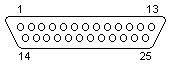
DB-25 Male
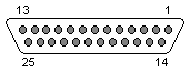
DB-25 Female
Here's a good set of figures for DB-9 male and female
connectors, as viewed from the pin side (not the solder side).

DB-9 Male

DB-9 Female
If you're using a serial cable or null-modem cable for
local serial connectivity or for modem replacement, you might consider
looking at the Traversix™
network connectivity solutions. You can use Traversix
ethernet-to-serial connectivity products to connect to serial-enabled
devices over the Internet, even (especially) when those devices are
located behind a third-party firewall.
|