|
Audio Connectors
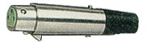
Two of the most common connectors used for professional audio are the XLR
connector and the 1/4" phone connector. Both have 3 conductors,
useful for handling both phases of a balanced line, plus a shield. Why do
most professional audio systems use balanced lines, you might ask. See below for an explanation.
XLR Connector
The origin of the XLR connector was the Cannon "X Series"
connector. It fit the demands of the audio community except that it
wouldn't latch into place, and could be easily unplugged. Cannon
rearranged the pins and added a latch. The new connector was called Cannon
"XL Series". Later, the female version was changed to put the
contacts in a resilient rubber compound. The connector was then called Cannon
"XLR Series". This connector soon became the industry's
standard and nearly every connector manufacturer copied the Cannon
connector. It became an AES standard in 1982 with the pin assignment as
follows:
| Pin |
Signal |
| 1 |
Shield |
| 2 |
Signal + |
| 3 |
Signal - |
|
|
However, there is a large amount of equipment in the US that has pin 2 and pin
3 reversed (i.e., pin 2 Signal- , pin 3 Signal+). When in doubt, read your manual.
Since the AES standard AES 3-1992 the three-pin XLR connector is also the
standard connector for AES/EBU digital connections (electronically balanced,
impedance 110 ohms). Also, Switchcraft offers a "mini" version of
the XLR connector, called the Tini Q-G.
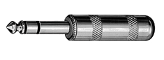
1/4" Phone Connector
For typical balanced lines using 1/4" phone connectors, you should
connect the positive phase signal line (hot) to the tip, the negative phase
signal line (neutral) to the ring, and the shield to the shield.
|
Pin
|
Signal |
| Tip |
Signal + |
| Ring |
Signal - |
| Shield |
Shield/ground |
|
|
Balanced Lines
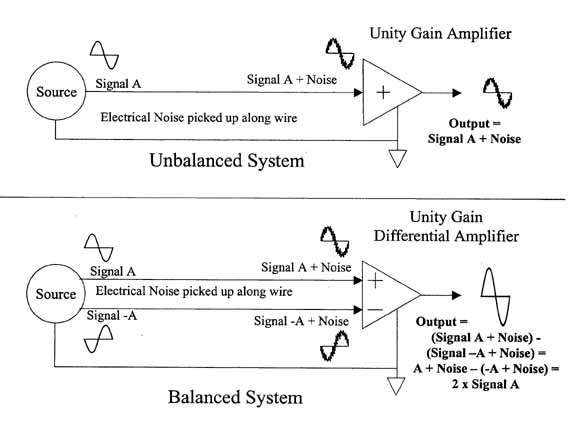
An unbalanced audio system consists of a signal source with a single output
referenced to ground (see "Unbalanced" figure below). The signal comes
from the output of the source, through the center conductor of the wire to the
input of the receiving amplifier. The foil or braid shield around the wire
provides the return path for the signal and also protects the center conductor
to some extent from electrical and radio interference.
Noise is added to the signal (from external sources) as it travels along the
wire, because the wire essentially as as an antenna. The resulting output
from the receiving amplifier consists of the signal plus the noise. This
noise might be so small that it can't be heard above the signal. In some
cases it is significantly louder. A number of factors affect the noise
level, including length of cable (the longer, the more noise it picks up), the
effectiveness of the shield and the particular characteristics of the
environment in which it is installed.
A balanced system is a little more complicated. Instead of a single
conductor plus a shield between the signal source and amplifier, there are two
conductors plus a shield. One conductor carries the main signal, while the other
conductor carries the inverse of the signal (180 degrees out of phase). The two
together are referred to as a "differential" signal.
As this differential signal is passed through the wires, they pick up the
same noise as the unbalanced signal does. By the time it reaches the
amplifier, both the positive and negative signals have the same noise added to
them. Keep in mind however that although the two source signals are 180 degrees
out of phase with each other, the noise is in phase.
These wires are connected to a differential amplifier which subtracts the out
of phase signal from the in phase signal. In the diagram below, these
signals are referred to as "-A" and "A" respectively.
When they are processed by the amplifier, the output is equal to A - (-A) which
equals 2A. Because the noise on the two lines is in phase, it is
subtracted from itself and thus cancels itself. This means that the signal
has doubled and the noise has been canceled out to zero.
Although other types of noise can also be introduced in a cable
(such as phase distortion, etc.), balanced lines do a very good job of removing
common-mode noise as described above. (Common-mode means that the noise is
common to both conductors.)
Also, note that to avoid ground loops, many audio engineers do
not connect the shield at both ends (for example, connecting the shield at
console, but not at the remote device). If you experience excess hum in
your audio installation, it may be due to improper or inconsistent grounding.
Of course, not ALL audio components support balanced
lines. In many cases, it is necessary to connect a device with unbalanced
outputs to a device with balanced inputs (or vice-versa). In such
cases, it's best to refer to the manufacturer's instructions. However,
there are several other solutions that you may want to consider. The
simplest is as follows:
Connect Signal+ of the balanced signal to the "hot"
pin of the unbalanced signal connector. Connect Signal- of the balanced
signal to the "ground" pin of the unbalanced connector. Connect
shield of the balanced signal to the "ground" pin of the unbalanced
connector, or if hum is added by doing this, leave the shield unconnected at the
unbalanced end.
Another technique is to use an isolation transformer, such as
those available from:
Lastly, if you're converting between unbalanced and balanced
lines, you may also need a level change as well, since many unbalanced lines are
run at consumer levels (nominally -10dbV), and most balanced lines are run
at professional levels (nominally +4dbu). A couple of manufacturers who make
level-conversion products are:
|