Pictures
Here are the picture-files to look at or to download:
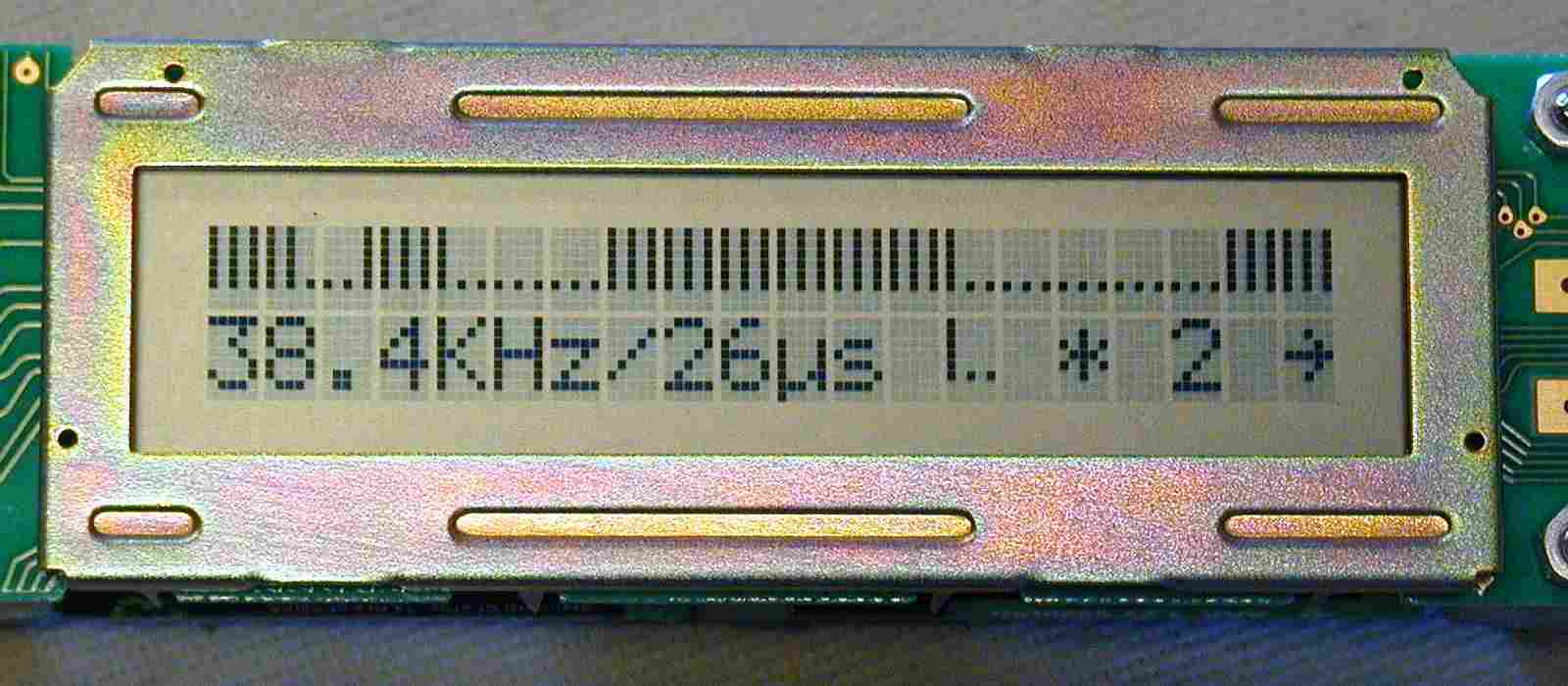
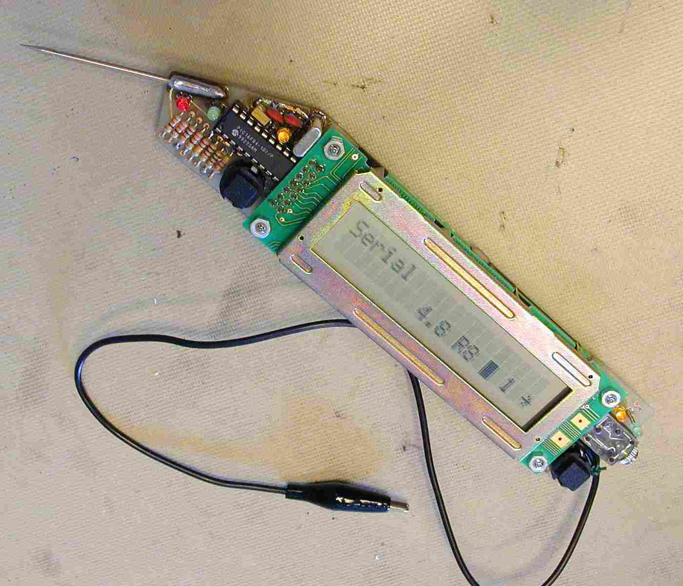
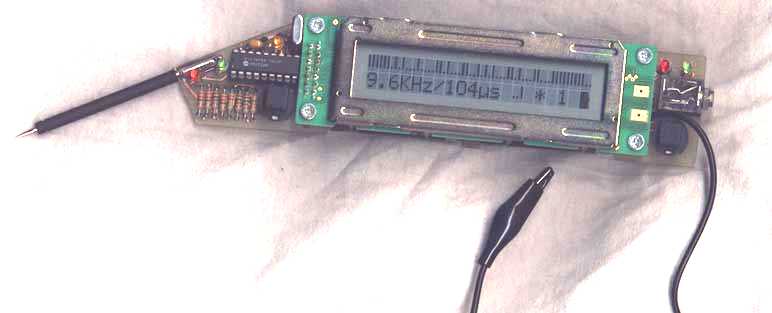
| display.jpg | This is a
close-up of the LCD when the instrument is in
"Analyzer" mode. We're looking at bit samples
no. 61 through 120 (window no. 2). Sample rate is 26µs
and the process was trigged at a high-to-low transition. |
||
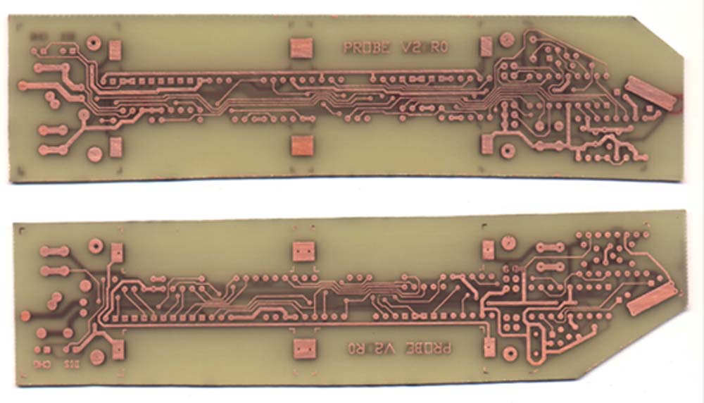
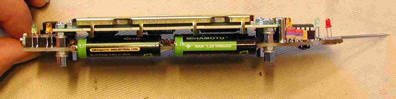
| Printed_Circuit_Boards.jpg | A picture of
two etched PCBs. The upper one shows the solder-side and
the other shows the component-side. |
||
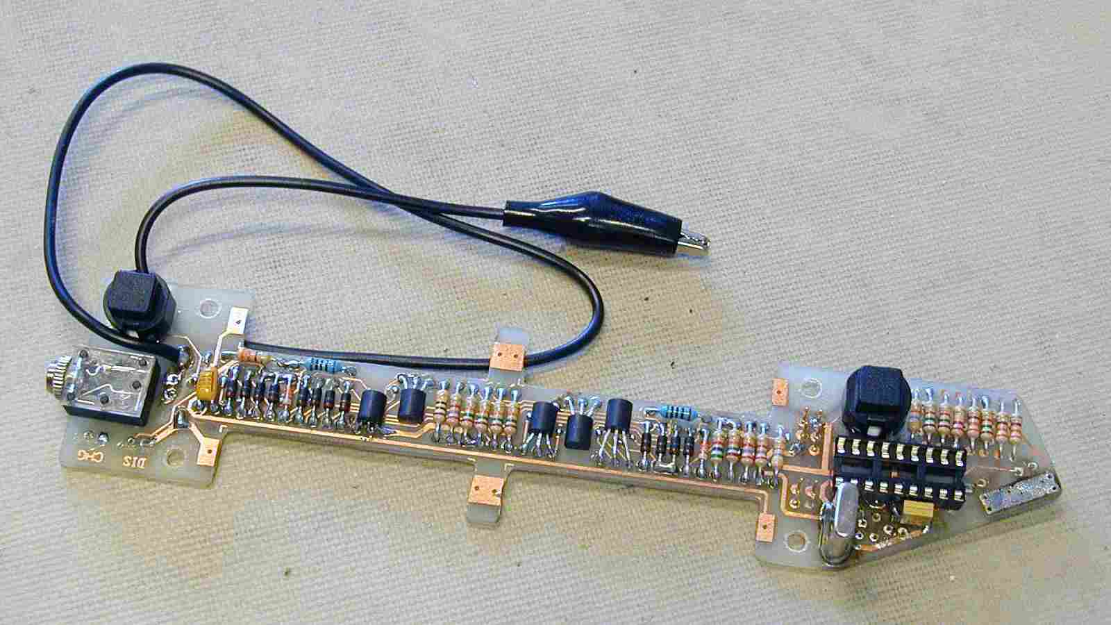
| halfway.jpg | The
instrument's PCB with most of the components soldered. |
||
| underside.jpg | Shows the
finished instrument from the solder-side of the PCB. You
can see the reset switch (S3) and the 33ohms resistor
mentioned in the Battery issues section. |
||
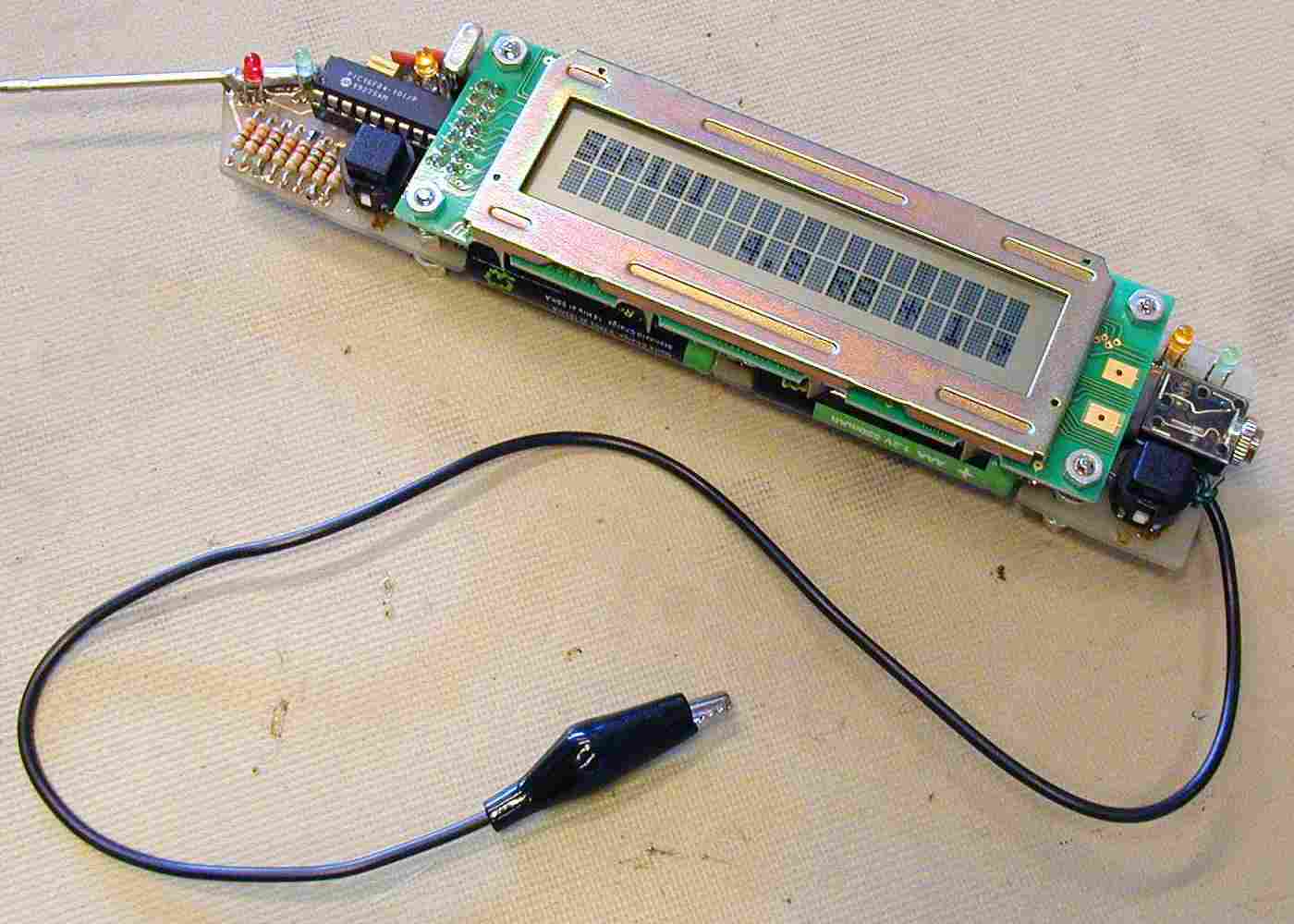
| sideview.jpg | This image
shows the instrument from the side. |
||
| finished-1.jpg | A picture of
the instrument with analyzer-data on the LCD. (The same things on the LCD as in display.jpg) |
||
| finished-2.jpg | This is
another version of the same image that is used as a
background for the main page: "Engineer's Assistant
- homepage". |
||
| finished-3.jpg | Just yet
another picture of the finished instrument. It has a
slightly different viewing angle than finished-2.jpg. |
||
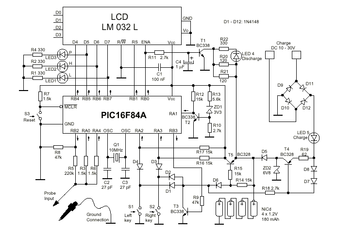
| schematic.gif | This is a
copy from the PDF-file. Is shows the schematic wiring
diagram of the instrument. |
||
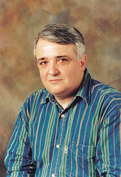
| Voja Antonic.jpg | Here is a
picture of mr. Voja Antonic, the man behind the
Engineer's Assistant. I found this somewhere at the
Internet. |
||
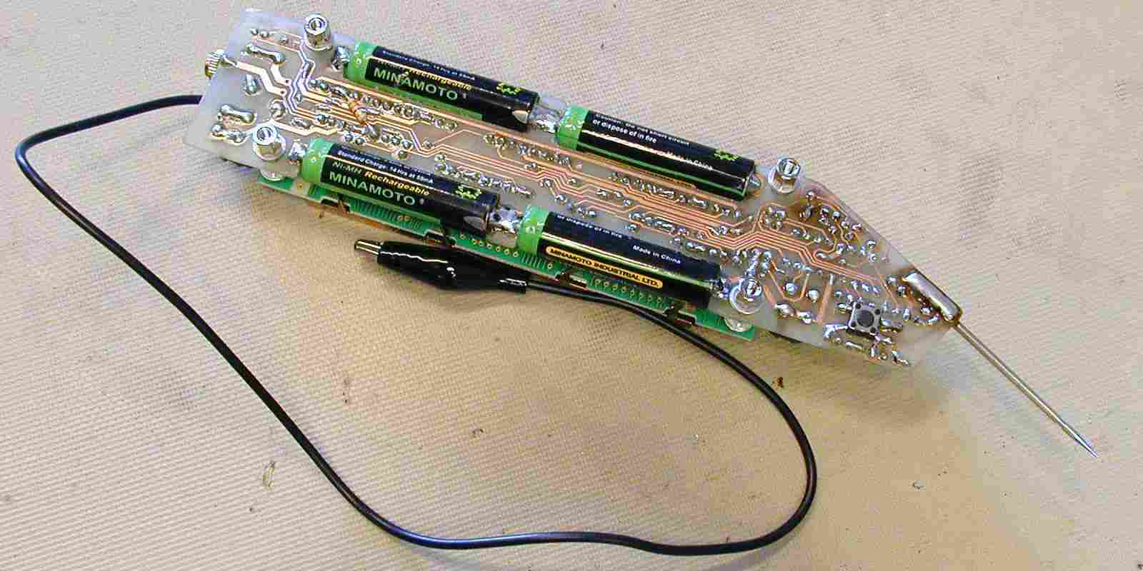
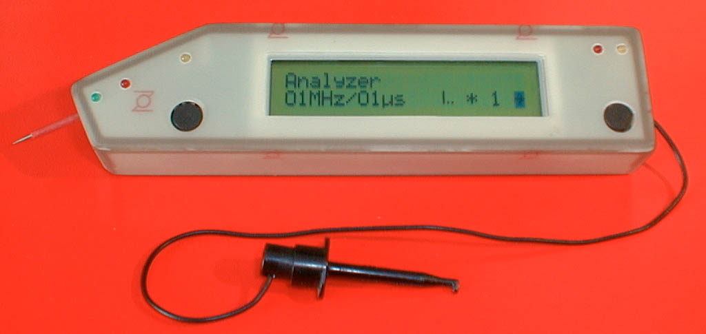
| probe1.jpg | This is a
picture of the author's finished instrument with a case
of PCB material (fibre glass). |
||
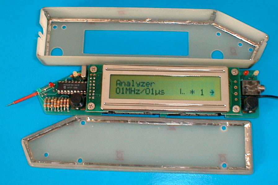
| probe2.jpg | Same as above
(probe1.jpg), but with the insrument case
opened up. It's easy to see how the case is soldered
together. |
||
| pov-ea.jpg | Per Otto Vangsnes' assistant. The picture is of low quality as it is taken with a low-budget scanner and a white T-shirt! The PCB is made of two single-sided fibre glass boards. |
If you have a picture of your own "assistant" that you would like to see on this page, feel free to e-mail it to me.
Erik Grindheim, 14.04.2000