Step Attenuator
After working on several receivers, I realized just how useful a step attenuator would be combined with my log power meter. Due to the "backordered" status of several of Mouser's 1% resistors typically used in the attenuator designs, I actually got very close to the calculated pad resistors by parallel combinations. The attenuator is more accurate as a result. I wired up the switches for 3 20dB pads, and 10, 5, 3, 2 and 1 dB based on the low power attenuator configuration from the ARRL Handbook. Since I used a long "u-locking" aluminum case, with rectangular holes cut by drilling and nibbling, I couldn't use the same method for switch isolation as in the copper PC board case from the Handbook. So, I prepared to do the partitions using a tin sheet lining, and tin partitions, etc, but then I noticed that Elecraft's new step attenuator is simply laid out on a PC board! Is "blow by" a concern at these levels? Don't know, but I decided not to take the chance.
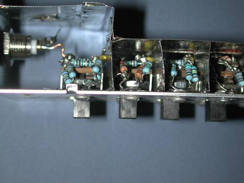
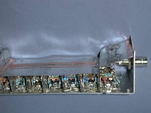
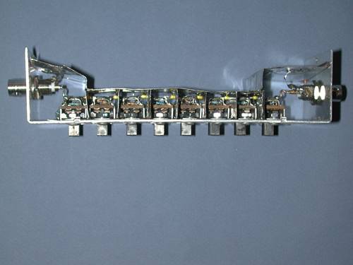
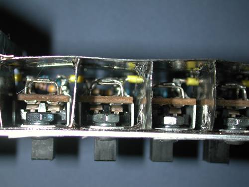
I installed two tin strips 1/2" wide between the switches and the aluminum box where the bolts go through, running the length of the box. Between each switch, I soldered a horizontal rectangle of tin to the strips, leaving about 3/16" clearance to the #14 insulated wire that I ran from the BNC connectors and down along the row of switches. Then, I made a similar tin barrier, notched in the middle of the bottom edge to get sufficient overlap, and soldered it to the lower barrier. The result is a vertical barrier between each switch, with a hole in for the wire to pass. Next, I soldered a "roof" over each switch, and finally, a tin wall on each side of the row of switches. Therefore, each switch has its own little isolated housing. Should stop some RF.
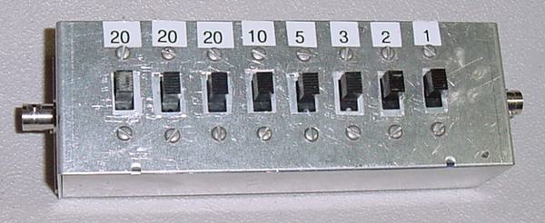
Below are the internal views of the step attenuator, prior to soldering the tin sides on the internal assembly. Click to enlarge.