30 meter Transceiver for Straight Key Night 2005
"Kitbashing" a Vectronics transmitter to make a useful rig
This
project is a 30 meter transceiver built for Straight Key Night 2005-2006. With only three weeks to build the SKN transceiver, I could
hardly come up with something original, so I decided to convert an
existing 20 meter Vectronics VXO transmitter to 30 meters, and I also did
some modifications to the rig. In the model railroading hobby, they call
this "kitbashing". I pieced together a receiver design based in part on
at least three of Dave Benson, K1SWL's designs (note the credit etched
into the receiver's circuit board), adding a highly-selective
triple-tuned receiver bandpass filter (design compliments of Jim Kortge,
K8IQY, who provided me with a design he had homebrewed) and a homebrew
4-pole Butterworth crystal ladder filter for the IF of 7.68 MHz. Wes
Hayward, W7ZOI gave me some pointers on the crystal filter, especially
the L-match networks to interface the filter with the SA-612 mixers' 1500
ohm impedance.
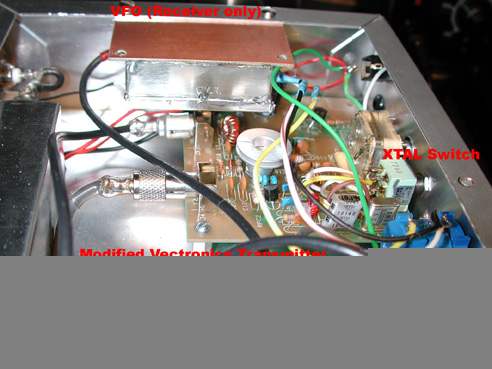
Vectronics Transmitter Mods
The
transmitter was modified to share the DC supply with the receiver, and
the T/R and muting circuitry was modified to use the capabilities of the
receiver. As in all of the similar Dave Benson designs, a sample of the
transmitter RF is sent through the receive audio chain as a "sidetone",
gated by an in-line FET via the keying circuit. This is far superior to
the normal modus operandi of the Vectronics transmitter with its direct
conversion twin receiver...no sidetone, and loud popping in the
headphones when the rig is keyed, an unpleasant experience. I removed the
push-button power switch, and power is supplied now to all modules via a
front panel toggle switch. I also removed the crystal select pushbutton,
and I mounted a DPDT switch for that on the front panel as well. In
accordance with good engineering practice, I also added a 33V 0.5 Watt
Zener diode across the collector-to-emitter of the 2N3053 PA to limit any
collector voltage swings that might damage the final.
Recent changes in
FCC spurious emission regulations require QRP rigs to meet the same
requirements as QRO rigs. Previously, with 5 Watts output or less, your
spurious emissions had to be only 30 dB below the carrier frequency
output. Now, the the requirement is 43 dB. I could have probably gotten
leniency under the "grandfathering" provisions of existing designs, but I
added a Chebychev 7-element low-pass filter which modeling showed that
the second harmonic to be well below the FCC requirements for spurious
emissions. This was later confirmed by testing on a spectrum analyzer.
The "trans-receiver" in one box would have to do until I could eventually
build a proper transmitter, sharing the receiver's VFO. The two crystals,
10.106 and 10.116 provide good VXO coverage of most of the CW activity. My original plans
were, if I had time, to add some circuitry to the Vectronics transmitter
before SKN. It would have entailed adding an SA612 transmit mixer, the
associated 7.68 mHz local oscillator, and a bandpass filter. That didn't
happen, so I instead have made a transmitter board to someday perhaps replace the
Vectronics board. It uses an SA612 mixer, receiving input from an
auxiliary output from the VFO, and the circuitry beyond the post-mixer
filter is similar to the Sierra from the ARRL Handbook, modified for 5
watts output using a different configuration for the PA
stage.
Some
photos from the project in progress are shown below.
Click on the photos for a higher
resolution image.
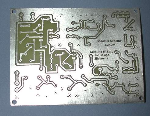
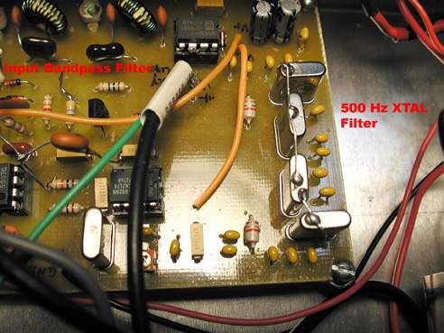
The
receiver main board
This is a
shot of the main board for the receiver. The VFO is a separate shielded
module in the case. The receiver board was created in Eagle Lite. I get
chided sometimes for building everything using CAD tools rather than ugly
construction, but my projects tend to get a bit ugly anyway. So far, each
board I've designed has been a prototype. I have yet to actually build
something that didn't need changing when I assembled and tested. To me,
CADding the boards is part of the fun. I've been using CAD programs of
one type or another since 1983.
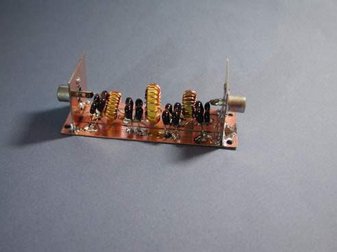
The low
pass filter, before final enclosure
Along with homebrew PC boards, I do
ocassionally build things ugly-style. The low pass filter is a Chebychev design with
a bit of ripple down around 7 MHz which is typical. I used standard value caps that
knocks the second harmonic down to -54 dB below the
fundamental.
As
installed, the filter is completely enclosed in PC board scraps and tin
sheeting and mounted on the inside back wall of the case. I used RCA
fittings internally and BNC's externally. Much cheaper that way. We have
a local surplus store that has the solderable jacks and plugs, and the
plugs have a nice long neck on them, perfect for complete shielding when
coax is soldered on. If you can't get that type, Wes Hayward, W7ZOI shows
a method on his web site for attaching brass sleeves to the back of the
plug.
ELSIE Plot
of the LP Filter
This is a
screen capture of the filter design from Jim Tonne's fine freeware ELSIE
program.
VFO prior
to having its roof put on
One
ugly-style VFO. It's a varactor-tuned Colpitts, using an MV1662 and a
100k pot at 8 volts regulated. I had the wrong polystyrene capacitors for
the VFO range, due to looking at the wrong schematic when I placed the
order. I made an adjustment by changing the toroid core type to T50-6,
and winding for 2.7 uH. When I built the VFO, the frequency range was
about 135 kHz too low, so I went back to my calculation spreadsheet and
the toroid chart and saw that I could hit the range dead center by
removing one turn from the toroid. The VFO is now set to tune from 2.421
to 2.458 MHz, which equates to 10.101 to 10.138 MHz. I have a trimmer
capacitor with an access hole in the VFO box that can swing the frequency
about 10 kHz. The wires penetrating the VFO compartment are reinforced
with heat shrink tubing, and I added hot glue to the holes to keep them
from moving around and possibly abrading the insulation.
I've added
some photos of the completed rig to this page, and the final photo shows
the tuning scale for the VFO. It is non-linear, which is characteristic
of this type of VFO. My SW20+ had the same extreme compression of the top
end of the range, and the expanded scale of the lower end of the tuning
range. I modified the VFO for the SW20+ for not only better
linearity, but a greater tuning range, and a method to switch in a
resistor at the cold end of the potentiometer that provides a nearly
completely linear range of 12 kHz, from one end of the pot to the other,
centered around 14.060, the QRP calling frequency. I based my experiments
on information from N7XJ in his ARS Sojourner article on improving the
SW40+. I don't need the additional range for this rig, but I will improve
the linearity.
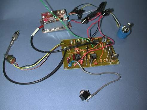
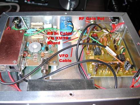
Receiver
main board and VFO set up for testing
After some
intense troubleshooting of various stages, the receiver began receiving
over-the-air signals on 3 feet of hookup wire from my daylight basement.
One definite snafu was in my schematic. I had a series resistor feeding
the 47 pF electrolytic cap going to the headphones jack designated the
wrong value. Audio, while still on the RF signal generator at the
receiver front end, was extremely low, although I had a nice signal on
the scope from the output of the crystal filter. Turns out that instead
of a 10 ohm resistor, I had a 1 Megohm one in its place! That will
definitely reduce the audio to the headphones!
All in
all, however, I am pretty pleased. This project was generally lacking in
my usual comedy-of-errors quotient. The way I designed the components to
go together using RCA plugs and jacks internal to the case, it was pretty
much plug and play from that point on. The flying green wire in the photo
connects to the keying circuit on the transmitter board, and is connected
to the W7EL-style gated FET audio mute circuit on the receiver
board.
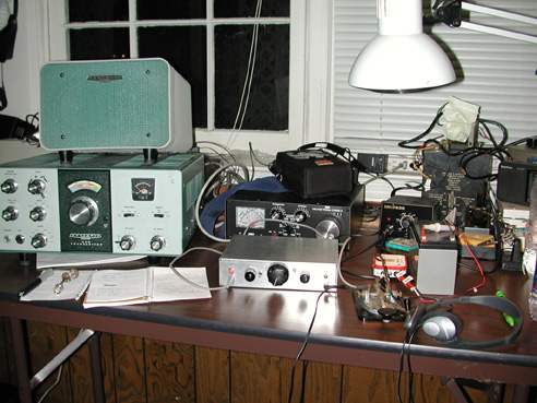
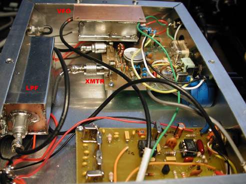
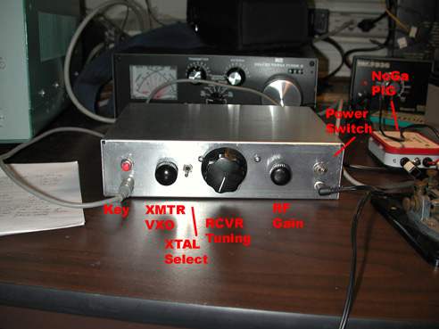
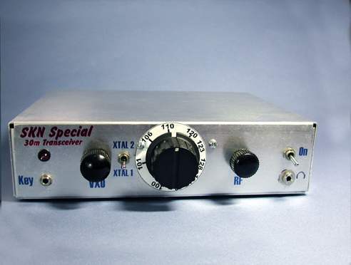
Finished
rig pics:
Here is an
assortment of photos of the finished (except for labeling and
beautification) 30 meter transceiver. I took a cue from Mike, KO4WX and
annotated some of the photos to identify different boards,
etc.
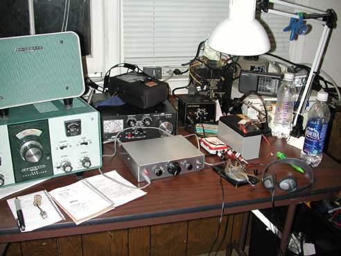
I was
re-doing my basement hamshack/electronics build and test area, and I had
everything cleared out of this area prior to getting this project going.
I'm now set up in front of the window, which will be the
permanent operating area, because I can feed the ladder line from the 80m
doublet in through a Lexan replacement window pane. After 25 years of
nothing but a 20 meter vertical, this is really going to be interesting.
In order to keep a sked Straight Key Night, I had to drag out of
the closet my only 40 meter-capable rig, my HW-101.
I would
like to thank the following people for their support and assistance on
this project: Jim Kortge, K8IQY for his design of the input double-tuned
filter, and Wes Hayward, W7ZOI for his patience answering some of my
questions regarding impedance matching the crystal filter using
L-networks, and for reviewing my filter design. I also would like to
thank Dave Benson, K1SWL for his designs of the SW-30+, the 40-40 and his
NN1G rigs, from which I borrowed heavily.