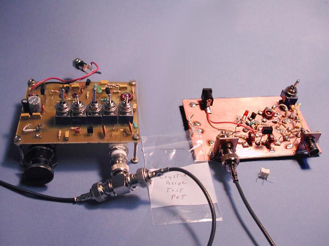
K8IQY-designed Precision VXO and Crystal Test Fixture
PVXO and crystal test fixture
The Precision VXO (Variable Crystal Oscillator) was originally kitted by the New Jersey QRP Club and published in "QRP Homebrewer Issue #9, November 2002, along with the circuit and description for the Crystal Test Fixture. I designed my own circuit board for the PVXO, working from the component layout drawing and schematic on K8IQY's web site (and in the magazine). I built the Crystal Test Fixture Manhattan-style, one of my first builds using that construction method.
The PVXO is connected at the BNC "Tee" connector to my Heathkit frequency counter, which reads to 1 Hertz. The Crystal Test Fixture has a built-in RF detector circuit at 50 ohms. This circuit may be bypassed by the toggle switch on the board to provide a straight-through signal to a 50-ohm terminated oscilloscope or other detection device. I used an inexpensive digital multimeter clipped onto the BNC input terminal, with the switch in the RF detector position. The multimeter was set to the 2000 mV scale, and it read out with 3-digit resolution (e.g., 81.8 mV). I initially tried my Velleman PC-based scope, but it unfortunately had only 2-digit RMS voltage readout resolution on the range that was required. As Jim Kortge points out in his articles on the equipment, the output is amplitude-independent; whatever device you can use, even a good quality analog multimeter, will work.
The PVXO frequency is adjusted to drive the crystal in the Crystal Test Fixture to determine its parameters. The five switches on the PVXO switch inductors into the circuit to resonate the crystal in the PVXO. A 10-turn pot provides a fine degree of variable frequency control output to the Crystal Test Fixture. The measurements required are the frequency at which the maximum voltage reading is obtained, which is the series-resonant frequency (Fs) of the crystal being tested in the test fixture, and the two frequencies where the voltmeter reads +3 dB and -3 dB from the peak reading (+/- 0.707 times peak). The difference in Hz between the +3 dB and -3 dB points is plugged into an equation provided in Jim's material. One other measurement is taken. While the crystal under test is at its peak reading for Fs, the crystal is removed and replaced in the socket by a 25-ohm potentiometer. The pot is adjusted to obtain the same voltage reading that was recorded at Fs, and then the pot is removed from the socket and its resistance is measured. This reading, Rs, is the series resistance of the crystal at resonance.
From the readings obtained using the PVXO and crystal test fixture, the series resistance, Rs, motional inductance, Lm and motional capacitance, Cm are obtained, along with the Q of the crystal. These are the primary parameters, along with the crystal's series resonant frequency, that are needed in selection of crystals for use in a crystal ladder or Cohn Min-Loss IF filter (one other important parameter, Co, the crystal parallel capacitance should be measured directly or estimated). The parameters can then be entered into a computer program such as Filter.exe (free, courtesy of Almost All Digital Electronics (www.AADE.com) to design the crystal filter.
While testing a set of 11.0 MHz crystals, I was unable to obtain a peak reading on the DMM with the tuning 10-turn pot in the fully clockwise maximum frequency position. The inductance setting was 6.9 uH (2.2 uH and 4.7 uH inductors switched in) and the maximum obtainable frequency from the crystal in the PVXO was 10,999,820. Reducing the inductance setting to 4.7 uH produced a frequency of 11,000,283 with the pot at the minimum setting, which was above Fpeak of the crystal under test in the test fixture, as indicated by further advancing the pot decreasing the reading on the DMM. Switching PVXO crystals did not resolve the problem.
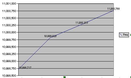
Frequency Plot Chart
The above chart shows the frequency plot, with the bend right at 10,999,820 due to switching from 6.9 uH to 4.7 uH inductance. After studying the circuit schematic, I decided to reduce the fixed 30 pF capacitor in parallel with the tuning diode to 27 pF. This moved the PVXO frequency down such that Fpeak was obtainable near the center of the tuning range of the pot. I was able to take data on a batch of 15 crystals with this arrangement. In Jim's published material, while crystal frequencies as high as 11 MHz can be tested, the equipment is optimized for lower frequencies. I discussed my results with Jim, and he suggested an alternative to changing the capacitor by putting two crystals in the PVXO in parallel...a QRP'ers trick to allow "bending" the frequency in a VXO more, one which I had forgotten!