Ā
Log Power Meter
Ā
This project is my build of the Logarithmic Power Meter featured in the June 2001 issue of QST by Wes Hayward, W7ZOI (coauthored with Bob Larkin, W7PUA). See Wes's web page at http://www.w7zoi.net for some errata from the QST article, as well as some application hints.
Since the initial build of the LPM several years ago, I updated the unit in 2016 with a new meter that reads directly in dBm. I was building my Poor Ham's Scalar Network Analyzer, described elsewhere on the site, at the same time. I bought a surplus meter with 1 mA full scale deflection, same as the RadioShack meter. Unlike the RadioShack meter and its 0-15VDC scale, I was able to remove the scale of the surplus meter for a new legend using patience and a razor blade The meter is from All Electronics, catalog number PM-376. As of January 2019, the meter is no longer in their catalog. You might contact them to inquire if any are available. Some other builders of the PHSNA have used that meter for the LPM. When I did the upgrade, I added a potentiometer to adjust the scale reading. That part of the circuit on the main board now matches the PHSNA LPM.
I added a closeup photo of the new meter to this page as the last photo. I added a couple of trim pots to my original homebrew board in order to set the deflection to correspond to the dBm points on the new scale, which I created with Jim Tonne's Meter Basic free version. With the exception of my retaining the LM358 opamp on my "hacked" PCB rather than the Analog Devices opamp of the PHSNA design, my updated LPM and the new one for the PHSNA are functionally equivalent. The calibration process established the accuracy of the readings within 1 dBm over the range of -60 dBm to -10 dBm. Like most builds of the AD8307-based power meters, the linearity drops off between -60 and -70 dBm. I consider the practical maximum power limit to be about +3 dBm; 10 dBm may possibly cause damage to the AD8307 log power IC. I generally attenuate the power ahead of the LPM such that the maximum reading is in the -10 dBm range.
I used the same calibration process that is used for the PHSNA LPM. I built a new LPM for that project in a larger case with the PC board provided by N5IB. The case was originally a PC power supply, and I built the circuity in a fully-enclosed copper-clad PC board box with feed-thru caps and a brass tube penetration. I also used a built-in battery source of 9VDC using 6 AA cells. The old LPM remains fully compatible with the HSNA equipment, and it is more portable.The log power meter can provide measurements from less than -70 dBm (0.1 nanowatt) to over +13 dBm (20 mW). The AD8307 demodulates the RF input to a DC voltage output with a slope equal to 25 mV per dB. Please refer to the QST article for further details on its use and capabilities.
I deviated a bit from the standard construction of the power meter as described in the article, taking to heart Wes' emphasis on shielding on his web page. I built a separate shielded enclosure for the front end circuitry, including the AD8307 log amp IC, and I fed power into this shielded enclosure, "the log-amp cabin" via a 1,000pF feedthrough cap, and fed the DC output via another 1,000 pF feedthrough. The only other penetration to the shielded environment is the BNC connector. I'll describe how I built the power meter in the following paragraphs, with photos of each step.
Click on the photos for a higher resolution image.
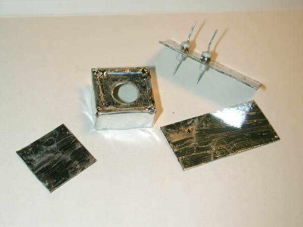
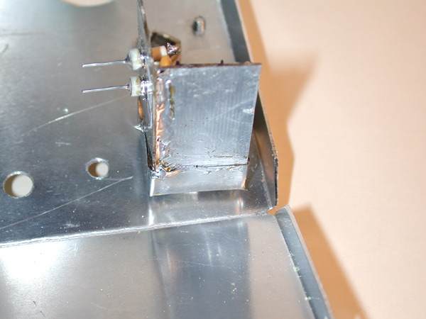
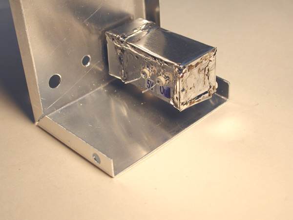
I used 1/32" double-sided pc board stock for the log amp enclosure. The basic pieces are the front and rear panels, the floor and one side. Later, I'll show how I used tin for the other parts of the enclosure.

The BNC connector is used to mount the front of the enclosure to the front panel. As you can see, I've applied tin strips around the front. To make sure that the BNC connector contacts the front panel on both sides, I used an extra-long BNC bulkhead connector, and I put an extra nut between the front panel and the front tinned copper section of the log amp enclosure.
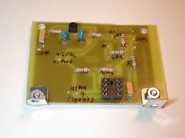
I designed a printed circuit board for the components not on the input/log amp board. This includes the LM358 op amp and the 5-Volt regulator circuits. I made the right-angle mounting brackets from some thin steel that I cut with my tin snips.
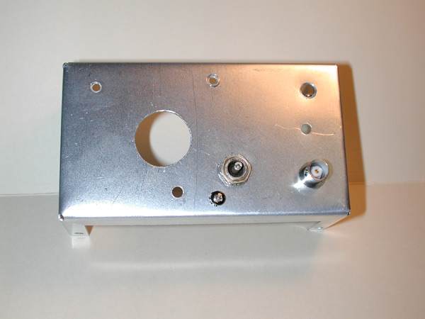
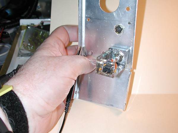
I used a stepped drill bit to drill the holes, and enlarged the hole for the meter with a rotary rasp mounted on the drill. This photo show the DVM atttachment point, which happens to be another type of 1,000 pF feedthrough capacitor. I think I'll be able to construct a DVM probe plug that will mate coaxially with the cap.
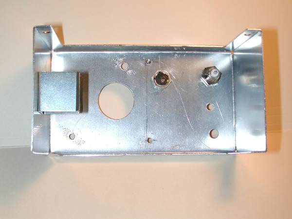
The view of the cabinet from the rear.
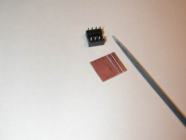
I didn't want to solder to the AD8307 log amp chip dead-bug style, so I made a Manhattan-ish pad to use with a DIP socket. The pad is to be soldered to the board, instead of being glued, so I provided extra solder points at both ends of the board. My concern was that glue might not adhere well to the tinned board surface, and that the heating involved with putting on the tin roof and wall might pop it loose. That happened to a low pass filter I built using the pc board and tin method.
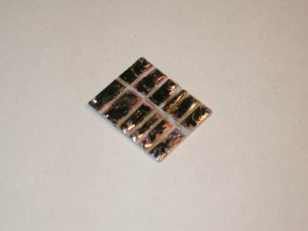
Photo of the completed log amp IC pad, tinned with solder, and checked for shorts. The dark color is an artifact due to the camera flash.
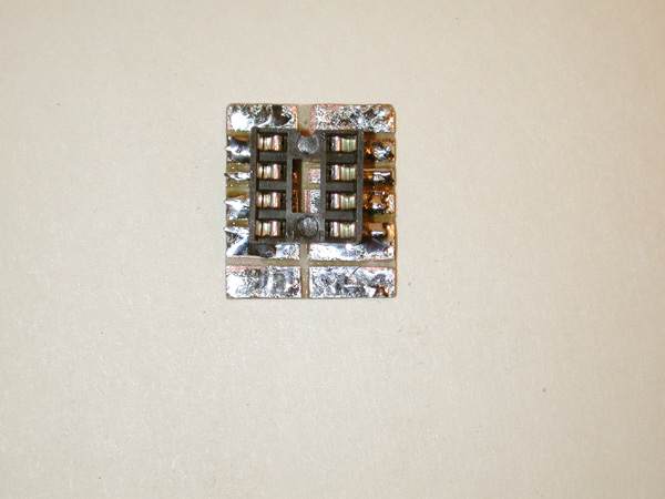
The IC socket soldered to the pad.
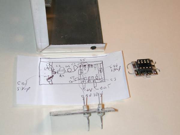
I drew up a rough to-scale layout plan for the board to ensure that I would have room to fit the input components between the BNC connector and the IC pad. You can see in the photo the grounding/pad position-locking component leads that I attached to the IC pad. The feed-through caps are soldered into their holes in the side wall.
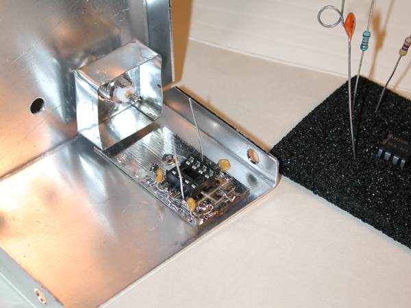
I checked the board for fit into the front log amp housing. I also had installed the capacitors that go from the IC socket pins to ground. Staged for installation are the front end resistors and the capacitor-inductor combo, C1 and L1.
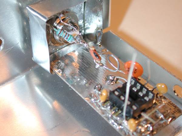
I tacked the log amp board in place and installed the front end components. I used a 1% 51.1 ohm resistor for R1, soldered from the BNC center post to ground. The RF input series path includes the parallel combination of R2 (470 ohms) and C2 (15 pF) and L1/C1, connected to pin 8 of the log amp. By the way, prior to finally boxing the board up with its tin sheathing, I rechecked L1 with a 3/16" drill bit for size.
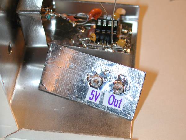
Before I went much further, I figured I should label the feed through caps on the outside of the wall. Otherwise, based on experience, after soldering everything shut, I'd surely have some anxiety over whether the power and DC signal current output feedthroughs were the right ones!
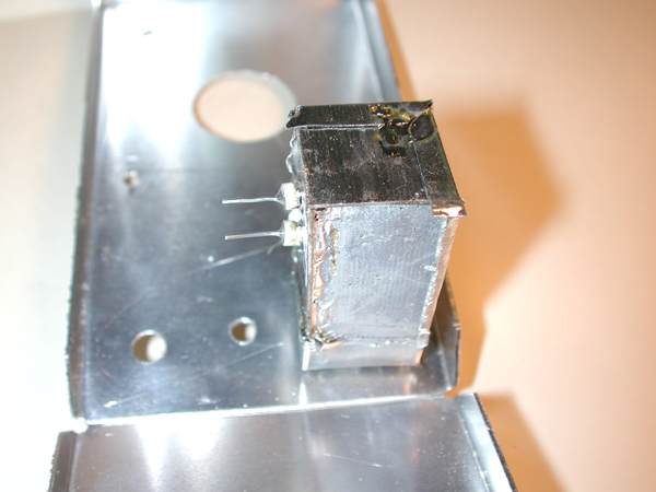
The side panel soldered in place to the front box.
This was the final good opportunity to insert the AD8307 log amplifier IC in its socket. Note that I used a wrist grounding strap while doing this.

I used a paper template to determine the size and bend points of the tin sheeting to be used for the top and right side of the "log amp cabin."
Side and roof panels soldered in place.
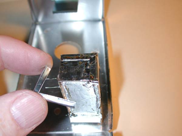
Since I used double-sided pc board, I could not effectively solder the outside of the joint and get RF-tightness; therefore, I made a trim piece out of tin, and soldered it over the remaining edges of the pc board. The "hobby tin" sheets, an Ace Hardware stock item, are soft and easy to bend, and they accept solder readily.
The "cabin" completely installed. The next steps were to connect the wiring for the power from the 9 Volt battery snaps to the switch and power LED and the main circuit board. Then, the circuit board connections were made with 5 Volt power to the log amp, the log amp signal, the auxiliary DVM connection and the panel meter. I used a 2.2k dropping resistor for the orange LED to make it bright enough to be visibly on, but to save on the current draw.
By the way, when I recently upgraded the LPM for a scale calibrated in dBm, I made no changes to the front end board/AD8307 enclosure. The only changes were some added components to the main board.
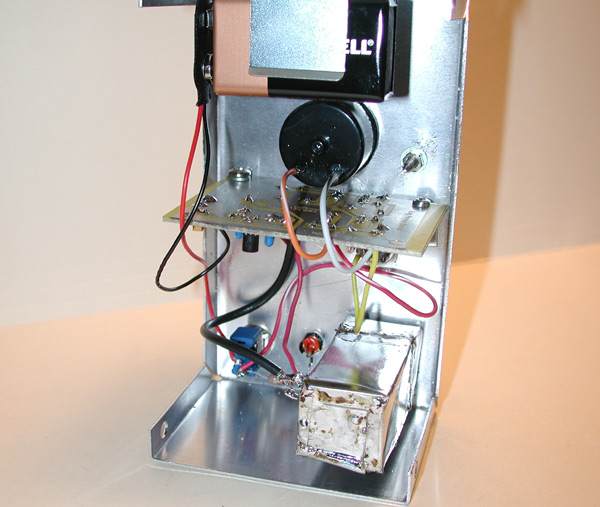
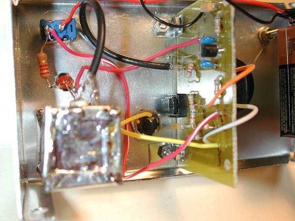
The insides of the completed power meter. Pretty simple, actually, considering what this device is capable of.
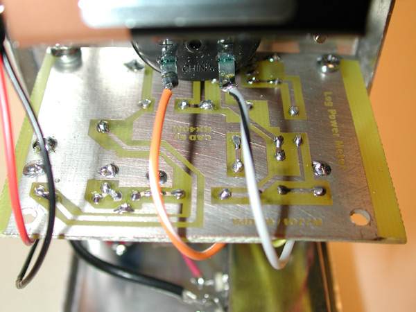
A shot of the bottom foil of the main PC board. Note the credit to the original circuit designers, W7ZOI and W7PUA. I put this information on all of my PCBs.
Wiring detail showing component side of the PC board. Probably overkill for what is a DC signal at this point, but I used RG-174 to route the signal from the log amp circuit's feed through cap to the main board.
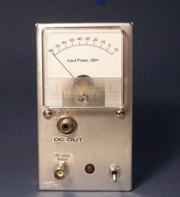
The completed log power meter. Due to my choice of the location of the 9 Volt battery holder, I put the calibration card in a frame on top of the meter.
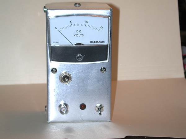
The meter, powered up. This is with the original meter from RadioShack. It shows a background reading of "1.5 Volts"...actually, since this meter is hooked up as milliammeter with a full scale reading of 1 mA, the current at this level is 0.1 mA. At this point I hadn't checked the calibration of the meter, but a look at the calibration chart in the QST article confirmed consistency with that one. The no-signal reading was less than -70 dBm at this point. After building the K8IQY -20 dBM test source, I confirmed that output read the voltage that corresponded to-20 dBM on the log power meter.
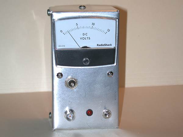
The new meter, showing the scale calibrated in dBm, alongside the new LPM. I built the second LPM along with the other equipment of the PHSNA. This replacement meter's original scale plate was not very that hard to remove. I carefully used a razor to remove the few spots of adhesive, making sure that I did not displace needle and meter movement. The RadioShack meter had much more adhesive, and it appeared to cover most of the plate; hence,the new meter from AllElectronics.com, catalog#PM-376. They are 2.4" square, 1 mA full scale, with 0-15 v and 0-3v scales. I used Jim Tonne's Meter program (the free basic version) for the dBm scale for the new meter.
Since my initial build several years ago, in 2015 I constructed a 10 MHz -10 dBm CMOS clock oscillator square wave generator designed by Bob Kopski, K3NHI. According to Analog Devices (and K3NHI for discovering that) the later versions of the AD8307 are accurate for a square wave signal only at that power level. In order to calibrate the slope of the meter for input signals less than -10 dBm, a sine wave is necessary. I built a 10 MHz -10 dBm sine wave generator based on a design of Todd Gale, VE7BPO. The sine wave generator is calibrated to the square wave generator. That allowed me to determine the calibration using 50-ohm attenuators of the input signal.
Final thoughts: Rarely does such a simple-to-build tool provide so much utility. Wes suggested that I build the log power meter to use in the interim until I could build a spectrum analyzer. He says that many of the same tests that use an SA can be performed with this meter, including testing and aligning filters, mixer performance, and many others, aside from the capability of measuring the outputs of low-level receiver stages and setting the outputs of VFOs and LOs. With simple additional accessories, the meter can be extended in range to +50 dBm, or 100 Watts. Next to my DVM and oscilloscope, this is the most useful pieces of test equipment I own. Although I now have a new LPM that I built for the Poor Ham's Scaler Network Analyzer, this one is much lighter with it's single 9 volt battery, smaller case and therefore much more portable.