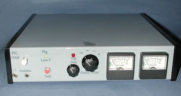
Enhanced Guppy-WaTTa-PiG Multifunction QRP Accessory
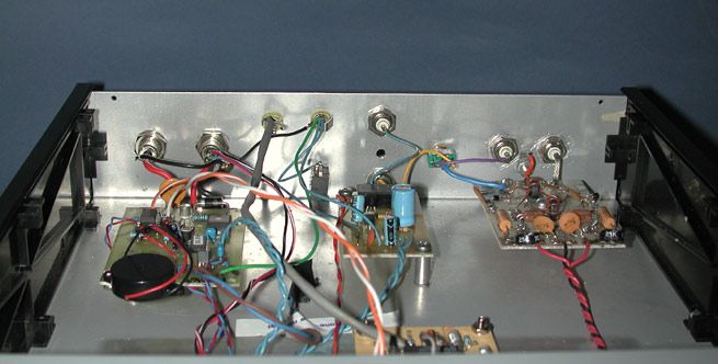
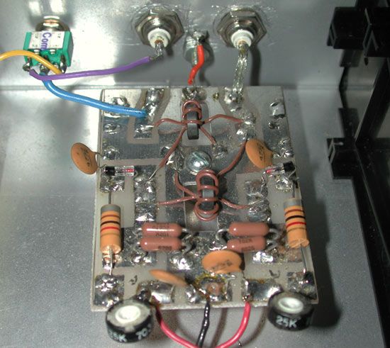
My friend Russ, AE4NY asked me for some help in integrating his homebrew QRP multifunction accessory made from three NoGa Kits: the Guppy T/R unit, the PiG and the NoGaWaTT. Russ wanted to be able to use the unit with several of his QRP rigs, including an SW40+, IC-703 and Vectronics transmitter and receiver separates. Mike, KO4WX and Steve, AA4BW had originally helped Russ put the unit together. In order to optimize everything, I decided to make the following changes and additions:
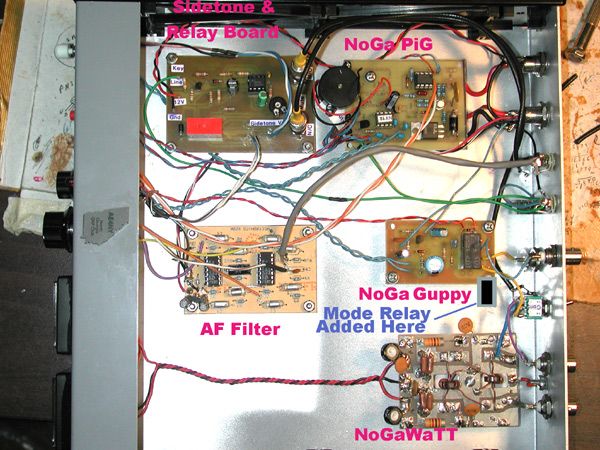
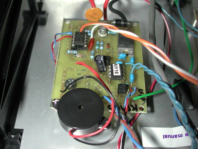
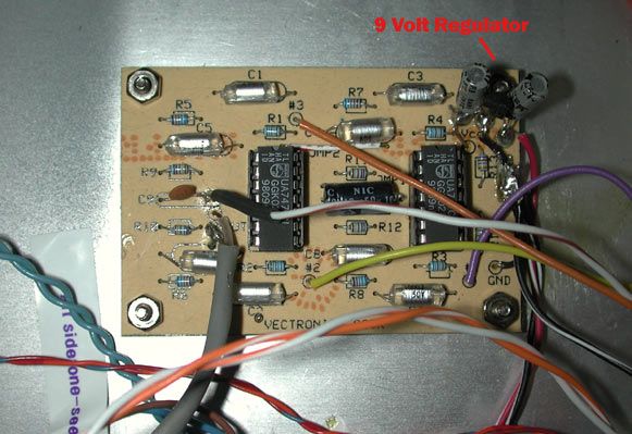
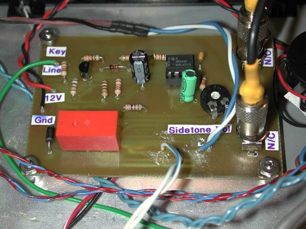
The project actually took place over a period of several months, as the individual components were relocated, and in case of the sidetone and relay board and MODE switch and relay, designed and built. Along with this project, I also modified Russ' 30 meter Vectronics receivers to operate from the nominal 13.8 Volt supply to the PiG protection unit. I did this by adding a string of 1N4001 diodes to drop the voltage down to the nominal 9 Volts that the receivers use (internally mounted 9 Volt batteries). When using the Vectronics twins with the Guppy-WaTTa-PiG unit, the unit should be powered from a battery, as the Vectronics direct conversion receivers are sensitive to power supply hum; hence the normal 9 Volt battery power. I homebrewed the Sidetone and Relay board, which is based on the sidetone circuit from Experimental Methods in RF Design, Figure 1.40. I had previously used this design in the 40 meter Challenger transmitter described on this site. I redesigned the board to accommodate a DPDT relay to provide receiver muting. Normally-open and normally-closed contacts were brought out to a pair of RCA jacks on the rear of the G-W-P. Those jacks are not shown in the photos, but they described in the PDF files "AE4NY Enhanced Guppy-Connections" and "AE4NY G-W-P Features Summary" accompanying the description and photos on this page. Links to the files are below.
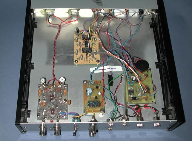
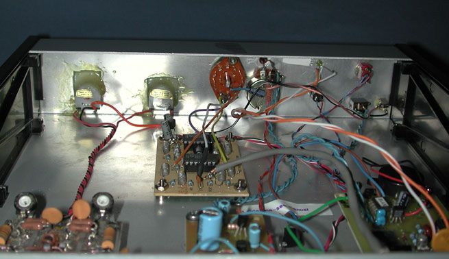
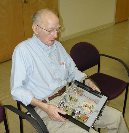
Below are photos of the inside and outside of the Enhanced AE4NY Guppy-WaTTa-PiG. Only the last first two photos in the bottom row show the Sidetone and Relay Board, and the location of the MODE Relay. The Mode switch (mini-toggle switch), not shown in the photos, was installed in the space to the left of the T/R Delay LED and pot. The last photo is Russ, AE4NY admiring his Guppy-WaTTa-PiG at the September, 2006 NoGa meeting.
Click on photo thumbnails to enlarge.


The following PDF and zip files are available for download:
"AE4NY G-W-P Features Summary"
"AE4NY Enhanced Guppy-Connections"
You'll need a PDF reader such as Adobe Acrobat Reader, or even better, the much less hard drive space-consuming SumatraPDF Reader. That's what I've used for several years.