Challenger 40 Transmitter
This project was the first equipment I built from EMRFD. I didn't have 40 meter low power capability, so I decided to build a rig. I laid out the schematic and boards in Eagle Lite for the transmitter and sidetone oscillator, and rather than depend solely on a DPDT switch for Transmit/Receive switching, I added a PC board relay, an Omron 6A-274 borrowed temporarily from my NoGa Guppy. I had to create that device in Eagle. I needed the extra switching, because I designed the rig to transceive with my Drake R-4B receiver. The transmitter has a receiver RF input from the R-4B via a BNC jack, an audio input from the Drake's audio output, and it supplies a mute signal via an RCA jack to the Mute RCA jack on the R-4B. When the T/R toggle switch is thrown on the transmitter, all of the switching takes place, the receiver audio is muted in the headphones (connected to the transmitter). Keying is heard by feeding the output of the sidetone oscillator to the headphone jack while in transmit. I had some difficulty making the "Spot" function work. The Spot switch supplies power to the oscillator and buffer stages in the Receive position of the T/R switch. After fooling around with blocking diodes to the various power feeds on the board, I decided to add a 3PDT switch in place of the double-pole one when I found that the Spot switch was actuating the T/R relay. My previous concern was that if I toggled the spot switch, accidently keying the transmitter would send 3 watts RF directly to the Receiver! I replaced the Spot toggle switch with a momentary push-button to make it more difficult for me to do that thing. Wes strongly recommends an add-on low pass filter to meet the requirements for spectral purity, as the 2nd harmonic is only around 30 dB down from the fnundamental (carrier). I initially designed an auxiliary filter using an aggressive 7-pole Chebychev shape, but I found that my 3 watts output was reduced to .7 watts as read on my NoGaWaTT, with a correspondingly high SWR. So, I rebuilt the filter using the values given in Wes's article in Chapter 1. I still wasn't satisfied with the standard value component results, so I modified the filter to accommodate trimmer capacitors. The screen shots from my spectrum analyzer show the rig with the on-board filtering alone, the untuned standard value modified filter, and the final adjusted filter. Note that I didn't have the cursors set on the untuned graph, but you can see that the 2nd harmonic is only about 25 dBc, and there is a spur of some sort at about 10 MHz. My SWR with the filter in line is still about 1.8:1, but I can get up to 4 watts with a clean-looking signal, but I've set it back to 3 Watts. My PC-based 16MHz spectrum analyzer shows the 2nd harmonic pretty far down compared to the rig's own filter alone. I intend to do some more experimenting, because the filter that I designed and built for the 30 meter SKN Special had a 2nd harmonic around 59 dBc. Some photos from the project are shown below. I did the front and rear panel art work in Photoshop, printed out on Glossy Photo paper,
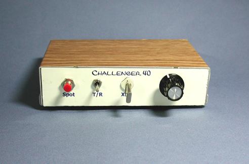
and applied with spray-on 3M adhesive.
Connections for power, phones and antenna - the other connections are for transceiving with the Drake R-4B.
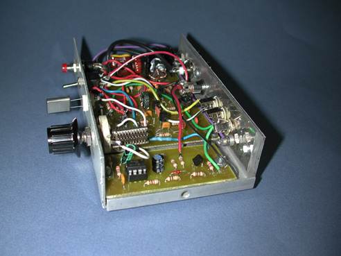
The rig's internals, prior to replacing the DPDT T/R switch with a 3PDT.
The VXO capacitor is actually too low in value to pull the crystal; however,
it works wonderfully in adjusting the level of the oscillator, and
consequently the output power of the rig! (not a feature I want).
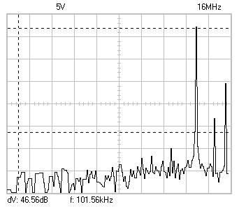
The spectrum analyzer plot of the rig with only the on-board filter LPF with standard value caps
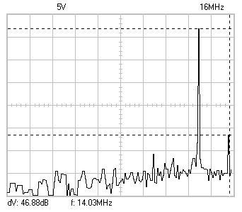
Trimmer caps added and adjusted I adjusted the trimmer caps while watching the SWR on the meter and the spectrum analyzer display.