Ā
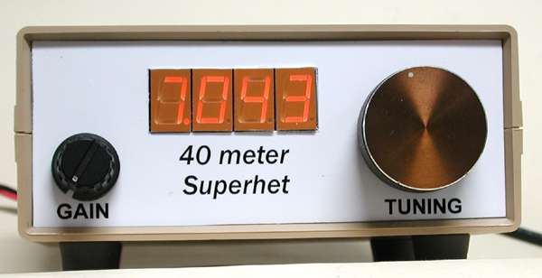
40 Meter Superhet
I was surprised to hear my grandson James repeating the "boot up" CW sent by the homebrew ELSIE LC meter one night a couple of years ago in my workshop. I set up the 30m SKN Special I built a couple of years ago in his room, and James started copying CW over the air and sending the characters back on a homebrew code practice oscillator I built for him. So, I decided to put off the plans for a 40m transceiver and build just the receiver for James. The receiver is based on the SW-40+ designed by Dave Benson, K1SWL and featured in ELMER 101, using homebrew CAD-produced PC boards for the VFO and the receiver. I bought and assembled one of Dave's SW-20+ kits awhile back, and I found the performance to be excellent.
I initially started building two receivers, the one shown here as well as an ugly-style construction "Popcorn" receiver" from the qrppops.net web site. I decided to go with this rig, rather than the homebrew Popcorn receiver, because I finally got this VFO to work right (had the tuning diode in backwards), and my Popcorn's VFO has issues. In my implementation of the the K1SWL-design VFO I used polystyrene caps, and it is very stable. I get coverage from 7.000 to 7.095 with the VFO. The second output of the Colpitts VFO, which would normally go to the transmit mixer, provides the input signal for the PIC-based DL4YHF-designed homebrew frequency counter. The original 4-pole Cohn-type crystal filter was intended to provide about 1 kHz bandwidth so James could hear more of the sounds of the band. However, I decided to go back to the base design using a 3-crystal Cohn filter. That's why I designed the circuit with plug-in crystal filters. The 3-pole, using parameters published by Jim Kortge, K8IQY gives better signal throughput. I also modified the AF bandwidth of the audio amp for a wider bandwidth. The rig sounds great now. No trace of the other sideband, and it's very quiet with respect to noise.
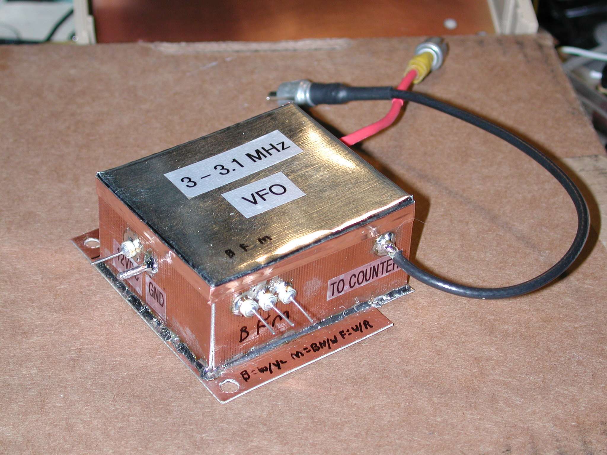
The surplus 4.0 MHz crystals are from a large batch of TV set pulls given to me by Harold, KE6TI, and when I characterized them on my PVXO test unit, they had very high Q and less than 10 kHz spacing among the four I chose. As a standard practice, I have started building all my crystal filters as plug-ins so that I can experiment with them. The BFO signal at 4 MHz is positioned on the skirt of the crystal filter for very good single-signal performance. The VFO and counter use feedthrough caps for power, and brass tubing is used for coaxial cable feed through. The rig covers the lower 100 kHz of the 40m band. With the digital readout, a 10-turn pot is used for tuning.
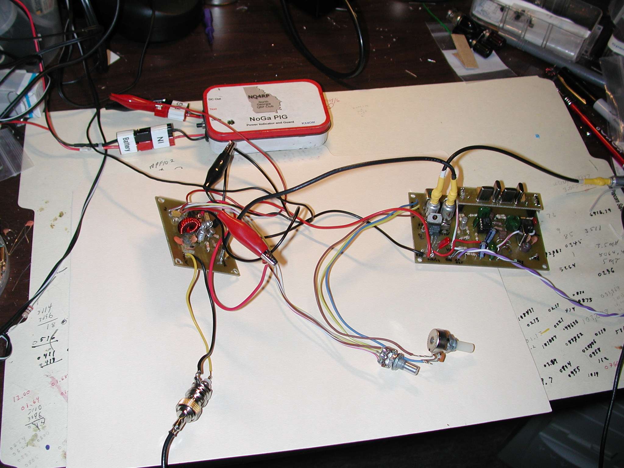
Below is the internal view of the receiver, and a closeup of the well-shielded VFO. The third photo shows the receiver and VFO hooked up for testing. Note that the 4-pole crystal filter is installed on its plug-in board during testing. Click to enlarge.
40 Meter Superhet Internals
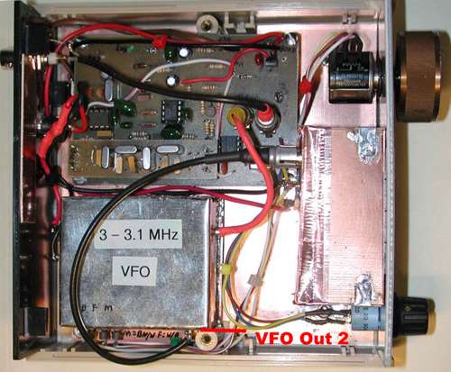
VFO compartment
Unit Testing