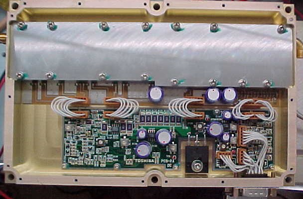
Toshiba Amplifiers for 3.4 GHz

This is the 20W model. The 40W amplifier has a swept
SMA RF output connector instead of the right angle connector.
This was posted to the WA1MBA
1.
Introduction.
This paper was created from several messages received on the Internet Lists in
September/October 2001 by Steve at DEMI, and K1DS. Important new info was
received from Owen, K6LEW in November 2001 on the importance of voltage
regulation and it is now incorporated in the text.
2. Checklist for Putting the New 3.456 GHz
Toshiba
Amplifiers on the Air.
There are two models:
a. 20 Watts output @ 3.456 GHz with 1 mW
input. (right angle SMA connector)
b. 40 Watts output @ 3.456 GHz with 1 mW
input. (swept right angle SMA connector)
Voltage: + 12.6 VDC (exactly)
3. Vendor Info on the 20 Watt
Amplifier
This is a Toshiba 20W Linear
Microwave Amplifier for use in the
3.44 to 3.68 GHz range. It is sold in the original manufacturers packaging.
Heat sinking: Required…it gets hot..
Size: 5" x 8" x 1 ".
Weight: About 2 pounds.
Input power: For full output, this is about 1
milliwatt or 0dBm.
Specifications: The specs on these amps are
very "tight" and are typically as follows:
Linear Gain = 42.5dB; Gain: Ripple = .1dB
Linearity is -45dB; Return Loss (in and out)=
25dB;
DC Power Supply current: Typically +12 VDC at
10.6 amps.
Power Jack: The DC power and control
connector is a DB-15 male.
DB-25 Pinout:
The ground is made from pins 3,7,10,11
connected together.
The +12VDC lead is made from pins 1,2,12,13 connected together
All VCC and ground pins need to be connected
to handle the 10.6 amps.
Pin 9 is the enable pin (TTL) which must be
connected to ground in transmit to switch the internal power supply on.
When pin 9 is not grounded, the 12 VDC supply
draws about 15 ma. and the
amp is in stand-by mode.
This is a Class A amp and as a linear
amp, it will draw
about 10.6 amps with no signal input.
Pins 4,5,8,15 are assorted alarm output pins
low true….no more is known..
Additional
information regarding the Toshiba 3.4 GHz amp (40W version – this should also
apply to the 20W amp)
Voltage + 12.6 V max.
Load SWR 2.0 max
Nominal power ~33dBm
Operating temperature +85 deg C max.
If temp >90degC shutdown - low power alarm = 0
Alarm resets automatically after a 10deg drop
The connection of the SUB-D 15 pin
connector:
1 +12,3 V
2 +12,3 V
3 GND
4 high output alarm - 1 up to 38dBm - 0 from 42dBm
5 SWR alarm - 1 >12dB
RL - 0 <6dB RL
6 not connected
7 GND
8 low output alarm - 1 Pout>10dBm - 0 Pout<6dBm
9 on/off control
10 GND
11 GND
12 +12,3 V
13 +12,3V
14 not connected
15 LED + R700-800 Ohm - 4-5mA
4. The 40 Watt Amplifier
This is a new Toshiba UM2683A 40W Linear Microwave Amplifier for
use in the 3.4 to 3.6GHz range. It is sold in the original manufacturers
packaging.
This amplifier differs from the
"2683B" "20W" version on other auctions
because there is a TMD0305-2 MMIC instead of the discrete circuitry in
the front end. The TMD305-2 part is a 3.4-5.1GHz amp with 2 watt
output and 22dB Power Gain. Turning the two pot's at the far left on
the lower board in the photo fully clockwise (shutting down the
attenuator) and peaking the power with the third pot (2nd and 3rd
stage bias) yielded 46dBm, 40 watts @ 3.456GHz using 12.0 -12.6vdc
(as measured at the connector) with about 0dBm input power .
Power supply requirement is 12.6VDC @ 15amps
after readjusting gain and
bias.
Heat sinking is required. The size of these
units is 5 x 8 x 1 inch
and weight is almost 2 pounds. Input power required for full output
is about 0dBm. DC power and control connector is a DB-15 male. Pin out
is as follows: Ground are pins 3,7,10,11; +12VDC are pins 1,2,12,13;
All VCC and ground pins need to be connected to handle the 15 amps.
Pin 9 is the enable pin (TTL) which must be grounded to switch the internal
supply on.
When not grounded, the 12 VDC supply draws
only about 15 ma. and the amp is in a stand-by mode. Since this is a linear
amp, is will draw about 14-15 amps without signal input.
Pins 4,5,8,15 are assorted alarm output pins
low true…no more is known.
Only new amps are being shipped.
5. Overall System View
When the amplifier is integrated into a
system such that relays, etc. are involved, the TX mode requires that the
amplifier Pin 9, the PTT, be grounded for the amplifier to amplify, i.e. turns
on the power supply built into the amplifier. For RX, removing ground
from Pin 9 places the amplifier into standby, drawing perhaps as much as 15 mA,
while the T/R relays all reposition for receive. There is no feed-through
via the amp. Changing from RX to TX involves just grounding Pin 9.
There are no relays internal to the amplifier
for switching RF between RX and TX, hence, external relays for switching
between RX and TX are required.
6. Critical Voltage Levels
Please refer to Step 14 (below) which is VERY critical. These amplifiers, especially the 40 W version, will go into "foldback" and be hard to recognize in so doing. The 12.6 VDC +/- 0.2 is critical because the output FET regulator has an extremely narrow window due to the heavy current drain.
If you allow your primary voltage to get outside of this window, the FET bias voltage , as adjusted by R 150 as measured on Pin 1 of the regulator interconnect to the amp section, you will note the need for drive in excess of 0 dbm for 40 dbm output (40 W). This is not good and indicates foldback which generates excess heat causing the "final" to generate more heat than it should.
These amps should draw 15 amps key down, not 14 amps, though some do vary. The set-up is simple enough but it has been necessary for several amps to be readjusted. This is because some operators did not see the importance of the relationship between the primary voltage at 12.6 VDC and the 10.3 VDC from the regulator controlled by R 150 and measured at Pin 1. This 12.6 VDC should be measured inside the unit with the cover off while the amp is under load, i.e. key down or Pin 9 grounded on the subminiature DB 15.
NOTE: You do NOT need any RF drive for this set up as the amp runs in Class A. If you have a power supply with remote sensing use it. If it does either voltage or current drain sensing, use voltage sensing. The voltage MUST stay steady at 12.6 VDC or something will surely be damaged, most probably the regulator, to be followed shortly thereafter by the costly output FET.
It is not necessary to monitor the drive level if you have reliable and repeatable equipment for the "exciter". Once you establish 0 dbm at the input port to the amplifier it should stay adjusted. If somehow the equipment is not reliable as to its output, and there is time to adjust, then monitoring the input level would be necessary. Most modern transmitting equipment of today is reliable such that once power levels are set, the input level to the amp should remain set.
One could easily think about installing two VDC measurement jacks and make R 150 an external pot so as to monitor and adjust both the 12.6 and 10.3 VDC (at the VR) levels. NO, the better choice is to monitor the output from a known and acceptable starting level. If you see the output begin to vary, then it is time to check the input level. To clarify this point, R 150 adjusts the output of the regulator BUT it does so in a very narrow window based on the primary input voltage of 12.6 VDC and the amount of current being drawn and R 138 will adjust this on the 40 W version.
In summary, this is to say that R 150 adjusts for 10.3 VDC ONLY when the primary voltage is 12.6 VDC with the amp under load (Pin 9 grounded) and the amp is drawing current. If 12.6 VDC in either direction is exceeded by about 0.3 - 0.4 VDC, adjusting R 150 will NOT regain 10.3 VDC.
Thus, make absolutely certain you have sufficient heat sinking mounted to the amp for any tests or operation. The devices in this amp are extremely expensive and will not accept much heat. This amp gets VERY hot very quickly without a heat sink attached. One could also use a muffin fan blowing across the heat sink. One of the "alarm" functions available on the subminiature DB 15 appears to provide a "temperature" alarm. It is not known what the temperature should be when this function is energized but there is a voltage on one of the alarm lines that appears to relate to an increase in temperature. This amp does not self protect, i.e. shut down, so be very careful !!! Perhaps the voltage could be used to control a relay which would remove PTT-ON from pin 9 but we do not know how much current it can handle. It may not be enough to control a relay, but it might control a NPNB transistor which could in turn control a relay, but this is not sure.
Conversion Steps.
- Obtain
power plug DB-15 male at RS or other. RS # is 276-1502 for about $2.00
- Find
and install heat sink size about 5" by 8"(size of amp) or larger
and muffin fan if desired
- Calculate
and obtain the attenuator value needed if you have more than 1 mw output
from your rig. FYI, the DB6NT units have about 200+ mw output and I will
use 24 db of attenuation.
- Connect
DB 15 power plug pins # 3,7,10,11 to ground.
- Connect
DB 15 power plug pins 1,2,12,13 as the + 12.6 VDC lead usable at 15 amps
load.
- Connect
a switch or relay to ground pin #9 for XMT.
7. Install antenna relay and
necessary D.C. power.
- Remove
cover to see the 4 pots R217, R210, R136 on 20 watt model, R138 on the 40
watt model, and R150. These first 3 are the first 3 counting from the left
and R 150 is directly to the right of the voltage regulator.
- Counting
from left, turn pots R217 and R 210 fully clockwise.
- Connect
exactly + 12.6 VDC power and power up.
- Measure
+12.6 VDC at pin 4 on P6 to ground.
- Connect
input signal on 3.456.1 GHz at the level of 1 mw or 0 DBM.
- Monitor
supply current and regulate to 15.0 amps with R138 on 40 W model and R136
on 20 W model.
- If
needed, adjust R150 for 10.3 VDC (CRITICAL) on right hand pins of P3.
- Peak
the power output with the third pot ( This is R 136 or R 138 ) to yield 40
watts output.
W7DHC has another method for power wiring instead of
using the 15 pin sub-D connector. It’s located on the Pacific Northwest Weak
Signal Page.
![]()