
How to Mount a Reduction Drive Assembly
If you look closely at the picture, you will see a cut-to-fit piece of PC board material, mounted in the bottom of the cabinet. This construction process is to mount individual circuit boards vertically on this board, securing them in place by running a solder bead along the pieces.
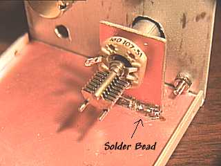
To mount the variable capacitor, simply cut a piece of copper pc board a bit larger than necessary to allow you to maneuver the shaft. Hold the board in place with your fingers while turning the drive assembly throughout a complete rotation to ensure freedom of movement without binding. If you feel any lateral pressure on the capacitor while rotating the drive, you will need to re-position and try again. Once you are sure the mechanism rotates freely, solder the entire unit in place.

If you have a 1/8" shaft capacitor as is often the case, you can use a sleeve to increase the diameter of the shaft to 1/4" by using an aluminum PC board stand-off. I found this in a bulk pack of a variety of sizes, so I cannot tell you what to buy individually. The stand-off did not fit perfectly over the 1/8" shaft without modification. Split the aluminum lengthwise with a dremel tool and then slide it over the capacitor shaft. Don't try to use the drive on a 1/8" shaft without a sleeve of some sort, as the capacitor will turn lopsided and will eventually bind and/or damage your mounting method.
Completed Unit
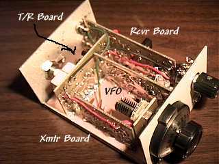
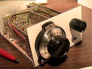
This is a modified Kanga "Oner", Direct Conversion transceiver for 40 Meters. Output is about 1/2 watt on a 12.8v supply. A "Novelty" Radio