My design uses an ATTiny13A processor and takes full advantage of its onboard peripherals and excellent power management. The I/O pins of this processor can source and sink enough current that no additional components are needed to drive the LEDs. Using the on-board timer and interrupts enables the entire circuit to power down completely when idle, eliminating the need for an on/off switch altogether.
A few sneaky tricks were used to enable the 14 lights and the "roll" button to be managed from a chip that has only 5 I/O pins. The first trick to recognize is that while a standard die has 7 pips, all but the center pip work in pairs, so there are really only 4 loads to control per die. For my dice, I connected each pair in series and used a resistor in series with the center pip to lower its brightness to match the pairs. For two dice, this gives us a total of 8 loads. We need to save an I/O pin for the "roll" button, so we only have 4 pins to control all the lights.
So how do you control 8 loads (two dies' worth) with only 4 I/O pins? That's the second trick, which is a special kind of multiplexing called charlieplexing. As in any form of multiplexing, there's really only one load switched on at a time. By switching loads fast enough, all the lights that need to be on will appear to be on at the same time.
Charlieplexing adds one more twist: since LEDs are diodes, they only draw current and light up when voltage is applied in one direction. So we can connect two series pairs of diodes back to back and choose which pair lights up by the polarity of the voltage applied. Each back-to-back pair of loads is connected across two I/O pins. Writing a "0" to one pin (effectively switching that pin to ground) and a "1" to the other (switching that pin to approximately the supply voltage) will light one pair of LEDs. Changing the first pin to a "1" and the second to a "0" reverses the polarity, causing the other pair of LEDs to light. If we don't want either pair lit, we reprogram at least one of the 2 pins as an input, sending it into a high-impedence state that neither sources nor sinks enough current to light the LEDs.
How many sets of LEDs can we control this way? The answer is the number of unique pairs of I/O pins, doubled (because we're using each pair in both directions.) Skipping the lesson in statistical math (look up "combinations" if you're curious), 4 pins will allow us to multiplex up to 12 sets of LEDs. That means we could even add a third die if we wanted to!
The last problem is how do we generate two truly random numbers between 1 and 6 so we don't end up with "loaded" dice? For that we get some help from the fact that the AVR chips are very, very fast. How fast? Fast enough to do millions of calculations per second! So we just have the program keep counting from 1 to 6 and we use the "roll" button to tell it when to stop counting. Since no human can consistently time a button push within a few millionths of a second, the results will be more than random enough for our purposes.
To keep the LEDs at a consistent brightness, I used a timer interrupt to control the multiplexing. Every millisecond, the interrupt service routine turns off one set of LEDs and turns on the next. That's at least 20 times faster than the human eye can detect, so all the intended LEDs will appear to be on at once. The timer interrupt service routine handles one other detail: it keeps a count of the number of times it's been called. This allows the program to know when enough time has passed to turn off all the LEDs and power down.
To power down the processor, we turn off all the LEDs and reprogram the "roll" input pin to generate an interrupt the next time the button is pushed. Then we stop the timer and command the processor to go into power-off mode. The ATTiny13A will shut down completely until the next time the "roll" button is pushed. The button interrupt will "wake" the processor and start the next roll of the dice.
Circuit schematic:

Single-sided circuit board layout:
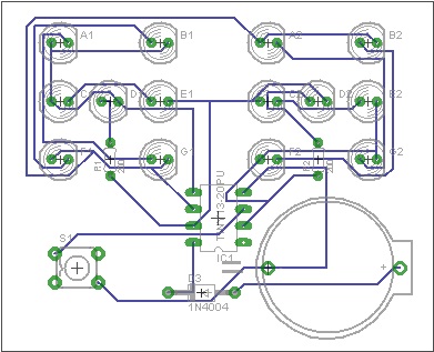
Here is Dice2.zip which contains the program code, the circuit schematic and a single-sided circuit board layout. The code was all written in C language, using the WinAVR tool suite. The schematic and board layout were done using Eagle version 6.
Drop me a note to let me know if you use my design. I'll also do my best to answer any questions and would welcome any suggestions you might have.