My project was inspired by two other QRP matchers, both based on a classic L-network design. Both matchers contain an N7VE-style resistive bridge SWR indicator. The N7VE design includes a small step-up transformer to drive the SWR LED, enabling it to work on extremely low power transmitters. A bit of experimentation showed that I did not need the transformer with my 5-watt radio, allowing me to simplify the circuit a bit.
One of my inspirations is the "Altoids Longwire Tuner" which used to be sold by Hendricks QRP Kits but was discontinued some time ago. It consisted mainly of a circuit board full of hand-wound toroidal inductors that could be shorted out one by one using standard PC pin jumpers. (QRPkits does still sell an L-network tuner called the "SLT" which replaces the jumper blocks with slide switches and has a fancy case in place of the Altoids tin.)
My second inspiration came from an interesting website called QRPme and is called the "Tuna Tunah". Rex W1REX likes to build all his QRP gadgets into tuna cans! I liked a few things in particular about his tuner design: first, it used off-the-shelf molded chokes for the inductors - less work and cheaper than the toroid cores; second, he uses toggle switches instead of slide switches - easier to mount and wire point to point; and third, he adds an additional toggle switch to move the shunt capacitance to either input or output, allowing the matcher to function as either an L network for matching high-Z loads or an inverse L for matching low-Z loads.
I took the capacitor switch idea one step further by using a center-off switch, so that it could be taken completely out of the circuit. This allows me to find the optimal inductance first without any influence from the capacitor. It should also help on the upper bands, where the stray capacitance in the switches and wiring could be sufficient by itself.
I started out by building the SWR indicator on a small piece of perf board. It is held in place in the box by pressing the LED into a suitably-sized rubber grommet. Two solid wires connecting the bridge circuit to the DPDT "Tune/Operate" switch provide additional support. Next, I carefully laid out a template of all the control positions on graph paper. I taped a photocopy of the layout to the top of the Altoids tin and used that as a guide to punch all the holes for the LED, switches and variable capacitor. All components except for the input BNC and output clip leads mount to the tin lid. This keeps all the connections short and easy to reach.
After punching all the holes, I mounted all the switches, the tuning capacitor and the SWR indicator assembly to the tin lid. The tuning capacitor is a 2-section Polyvaricon consisting of two 270 pF sections and 4 separate trimmers. For this project, I paralleled the two main sections, giving me a maximum capacitance of 540 pF. All 4 trimmers were set to their fully open (minimum capacitance) state. The capacitor mounts to the tin lid using two 2.6mm metric screws. One must take care not to turn these screws in far enough to interfere with the capacitor plates. Because the metal in the mint tin is such a thin guage, the shortest screws available were still too long so I had to add a 1/16" nylon washer under each screw.
The inductors are wired directly across the switches, using the extra lead lengths to "daisy chain" each inductor and switch to the next. This was a bit of a challenge because of the close switch spacing and the super-tiny toggle switches I used. Each switch has to hold two choke leads on one of its terminals and they barely fit through the holes!
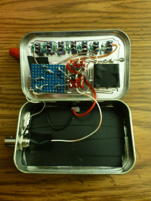
After completing the inductor chain, I wired up the rest of the interconnections on the tin lid using short lengths of stranded wire. My final step was to connect the BNC jack and the antenna clip leads. The input BNC jack is mounted on one side of the Altoids box. The antenna clip leads enter through a small rubber grommet at the rear, with a nylon tie wrap acting as a strain relief.
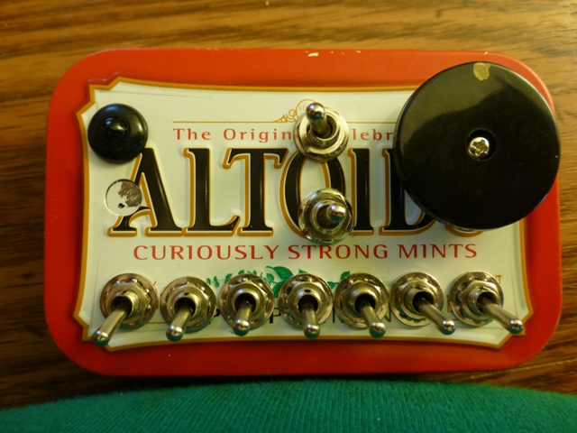
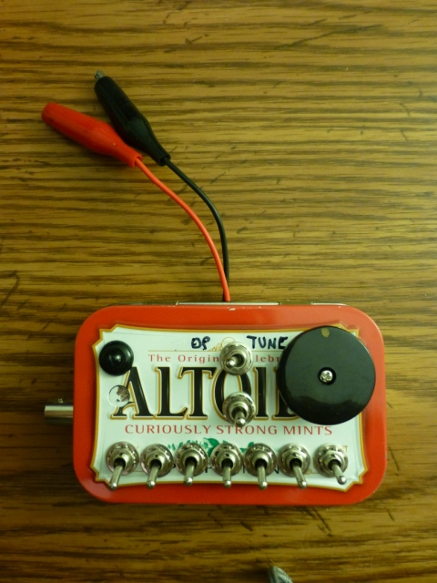
Here's how the controls are laid out. The on top is the "Tune/Operate" switch that takes the SWR bridge in or out of the circuit. Below it is the capacitor switch: Left = input (inverted L), Middle = out of circuit, Right = output (normal L). To the right of these switches is the tuning capacitor and to the left is the SWR LED. I added a dot of paint on the tuning knob so I can see where the capacitor is set. The row of 7 switches along the bottom add inductance and are ordered from highest to lowest.
Here's how the inside of the lid looks before wiring.

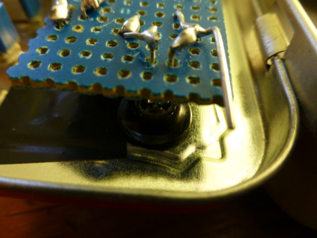
Here you can see how the LED was press-fit into the grommet in the Altoids lid. A 5mm LED is a snug fit in a 1/4-inch grommet.
The inductors sit in the space between the switches. Here you can see my "zig-zag" wiring technique. Like most toggle switches, the contacts work opposite the terminals, so with the switch "up" the inductor is included and with it "down" there's a short across it.
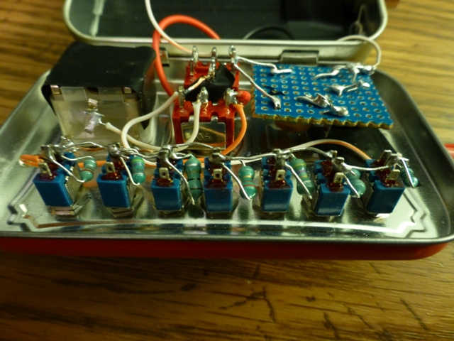
Here all the wiring is finished. Notice that the tin lid is grounded near the tuning capacitor and the tin body is grounded by the lug on the BNC input connector.
One more, all buttoned up and ready to go on the air!
Drop me a note to let me know if you use my design. I'll also do my best to answer any questions and would welcome any suggestions you might have.