9.2 METER (30 Ft.) DIAMETER DISH PROJECT
FOR EME AND RADIO ASTRONOMY
Figure
#1
Figure #2
Figure
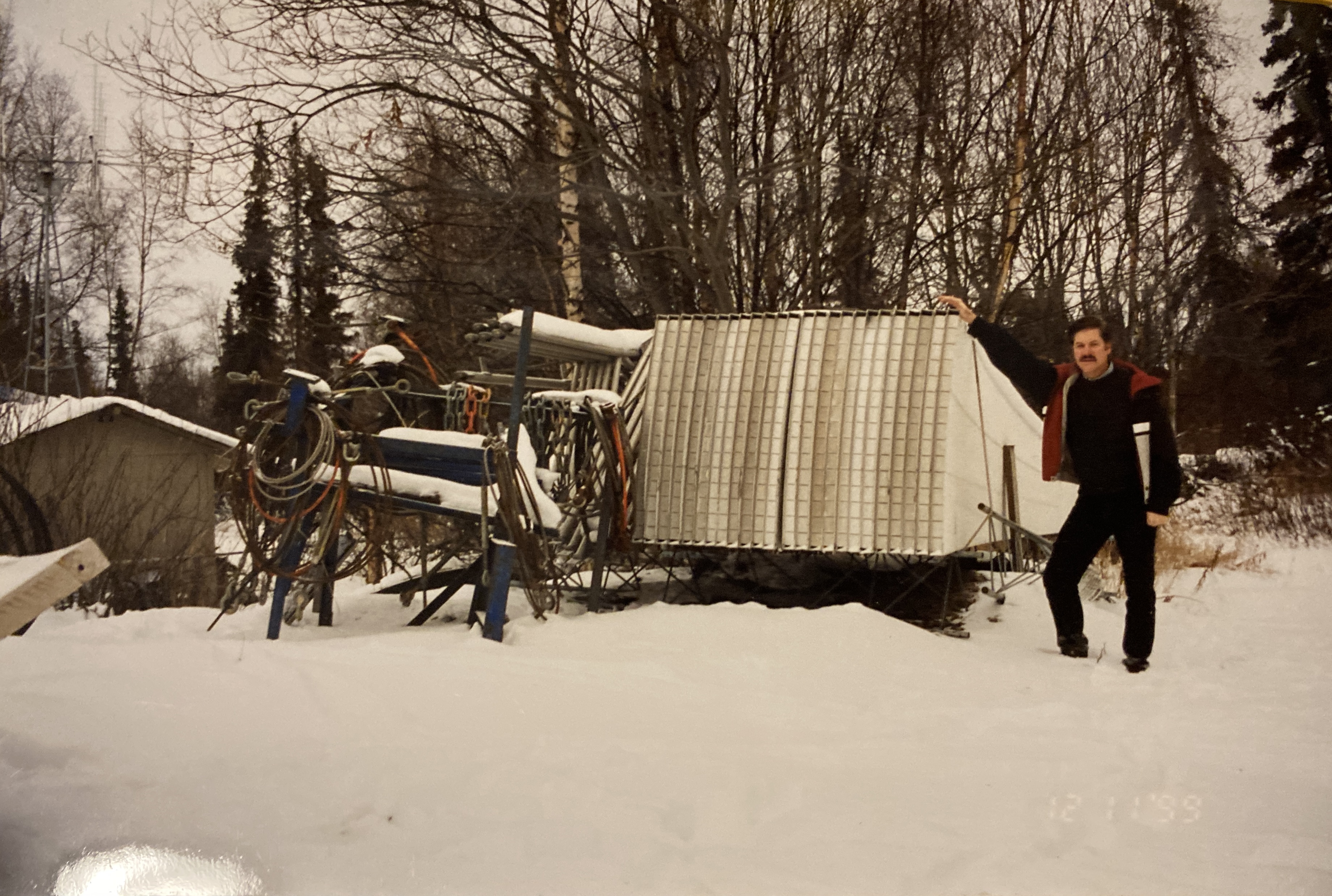
#1.
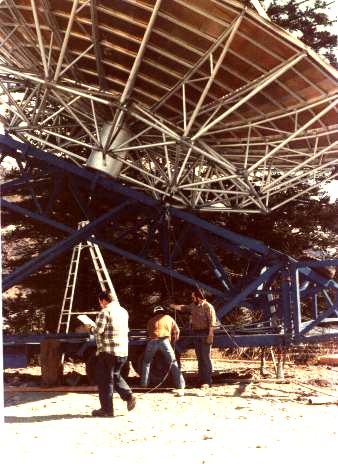
This is a transportable earth station antenna I obtained from surplus. It
normally would deploy on a trailer as shown. The trailer must be securely
fastened to the earth before any assembly can begin. This shows the
antenna as it is about to be raised for the first time. Picture was taken
back in the mid 1980's. This transportable earth station was originally
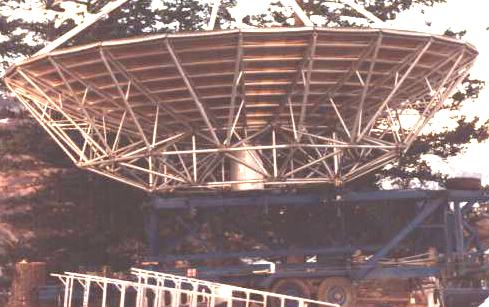
built by Comtech. Figure #2.
Another shot of the antenna after assembly prior to raising.
Figure #3
Figure
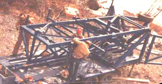
#3.
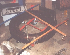
This the steel beam and angle iron construction which fastens to and supports
the aluminum trusses. The dish consists of 24 aluminum panels.
Trusses and panels alone weigh 2400 pounds.
PERMANENT
INSTALLATION: I plan to
significantly modify this antenna structure for permanent mounting. This
sketch in Figure 4, shows the current portable
design. The dish mounting structure is actually part of the
trailer. I have cut off the back of the trailer that includes this
structure and will eventually mount it on top of a tower. The elevation
mechanism uses a 20 ton actuator (jack screw).
Figure
4.
The sketch
in Figure 5 shows the octagon structure of the 8 primary trusses and the
connection points from the aluminum to the steel. There are three intermediate
trusses between each primary (not shown).
Figure
5.
Figure 6.
Figure 6 shows the planned
configuration (To be revised for piling foundation). I plan to mount the rear of the
trailer on a 30" thrust bearing as shown on the sketch for mounting on the
tower. I have shortened the three main steel support beams by 52"
to improve the mechanical advantage for the elevation system. The jack
screw which came with the unit is a 20 ton unit with a hand crank which
requires 1230 cranks to go from 0 to 90 degrees. Azimuth and elevation
will be motorized and computer controlled. Target rotation speeds are
0-90 in 2 minutes and 0-360 in 5 minutes.
The tower
is a triangular 6 foot face with 8.625" diameter legs of 0.322" wall
thickness, rising to 12 ft. above ground, driven to 18 ft. below ground.
I plan to design for maximum windload in the zenith
position, since I will not operate during any appreciable winds. The
following sketch is the antenna in the zenith position.
Figure
7.
Tower Construction
Details (Old version prior to the tubular steel design - see STATUS):
Dish AZ/EL Mount
Construction Details (This one is current):
Windload and tower design details (To be revised for pilings):
WINDLOADING
AND FOUNDATION CALCULATIONS
The
following assumptions were used in the calculations:
1. Design windspeed = 50 lbs/sq.ft. (approx. 120 mph)
2. Two
legs of the tower face away from maximum wind direction.
to reduce potential for buckling of the tower.
3. Design
is with antenna parked (EL = 90; AZ = 150 +/-10)
(Historically all winds in excess of 30 mph are from this direction)
4.
Concrete weight includes re-bar
[1] Area of a parabolic
section = 4/3 depth X radius
55"
X 180" X 4/3 = 91.66 sq. ft.
Reduce by
factor of 0.66 for cylindrical surface
91.66 X
0.66 = 60.5 sq. ft.
Windload = 60.5 X 50 =
3025 lbs
Moment =
23' X 3025 = 69575 ft-lbs
Weight
= 1344 lbs
[2] Perimeter Area of
Truss = 82 sq. ft.
Reduce by
factor of 0.50 for non-solid surfaces = 41 sq. ft.
Windload = 41 X 50 = 2050 lbs
Moment =
19.5' X 2050 =
39975 ft-lbs
Weight
= 1056
lbs
[3] Steel Mounting
Structure Area
Aprox. 40 feet of 4"
tubular steel = 13 sq. ft.
Windload = 13 X
50 = 650 lbs
Moment =
15' X 650 = 9750 ft-lbs
Weight
= 2800
lbs
[4] Tower (exposed)
Area
3
X 12' vert. + 4 Horiz. + 12 diag = 31 sq ft
Windload = 31 X 50 =
1550 lbs
Moment =
6' X 1550 = 9300 ft-lbs
Total
Tower Weight =
2452 lbs
(Including
buried section)
Dirt [B]= 9' X 9' X 4' X 95 lb/ft +3933 [C] =
34,713 lbs
Concrete
[A] = 9' X 9' X 2' X 150 lb/ft3 = 24,300
lbs
Total Overturning moment at
tower base = 128,600 ft-lbs
Total Weight = 66,665 lbs
Counterbalance = 4.5 X
66,665 = 299,993 ft-lbs
Safety factor = 2.33
The dish AZ/EL mount will
be fastened to a thrust (slew) bearing which was removed from a National 700
series 17 ton boom truck. It is manufactured by Kaydon
and is 29.5 inches in diameter and weighs 263 pounds:
FEED MOUNTING:
ANTENNA
LOCATION:
I have explored any zoning,
covenants, codes or restrictions in my area, and I have consulted an attorney
regarding any problems I might have with the erection of such a large
structure. We have found nothing to prohibit the installation. I have
reached an agreement on the location with the one neighbor who is affected. The
figure below shows the plot plan.
Schedule:
I plan to frequently update
the status of this project on the following page: STATUS
Stay tuned for future details
on motor drives, gear ratios, braking systems, position indicators, power and
RF cabling designs.
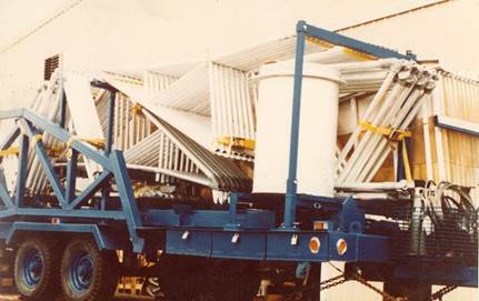
The aluminum sections and
trusses were stacked as shown in the picture until July 2000.
Please send any comments to
Mike ![]()