BY
Michael A. Czuhajewski WA8MCQ
7945 Citadel Drive
Severn, MD 21144
This is 1995, but the venerable Heathkit HW-7 transceiver is still out there, and I see ads for them from time to time. This was the first of three QRP transceivers that Heath sold, designed back in the days when direct conversion receivers had a well deserved bad reputation (much worse than they do now). In comparing the various Heath HW-rigs in 73 magazine several years ago, Mike Bryce, WB8VGE, said the receiver in the HW-7 "sucked canal water." Those who have operated HW-7s know that he was being kind.
DC RECEIVER PROBLEMS
Many people don't like DC receivers today because you can hear signals on both sides of zero beat, but trust me, that's nothing compared to some of the other problems they used to have. Early DC receivers suffered from a number of worse maladies; these included massive hum when using AC power supplies and tuning the preselector just right ("tunable hum"), as well as AM detection of shortwave broadcast stations. The hum could be worked around by using batteries, by using a bifilar wound choke in the power lead from an AC supply, or bypassing the diodes in that AC supply with disc capacitors.
However, there was not much that could be done about the shortwave stations; that was caused by AM detection in the receiver, and no matter where you tuned in the band it was always there, across the entire dial. It was a constant background companion, Father like having a radio going on the other side of the room. The cure to these problems was pointed out by W7EL in his August 1980 QST article, "An Optimized QRP Transceiver", and also by K70WJ in his July/October 1986 QRP Quarterly article, "A High Performance Direct Conversion Receiver". (That's not a two part article; this was the year the QRP Quarterly skipped a beat for some reason and missed an issue.)
The problems didn't exist in just the HW-7, either -- the early TenTec PM- series used essentially the same design in the receiver and had the same problems, as did many homebrew rigs of the day.
The common factor was that all of these used dual gate MOSFETs as a mixer. Those provide conversion gain, but have an unfortunate side effect-they also make good square law detectors, and provide envelope detection of AM signals. Wait a minute-some older commercial receivers and transceivers used dual gate MOSFETs as first mixers and yet they don't have shortwave BC stations blanketing the dial-how do they get away with it? The key is that those units are all superhets; the MOSFET mixers are detecting the AM signals all right, but the output of the mixer goes to an IF amplifier, and an IF amp tuned to 455 KHz or somewhere in the MHz region certainly isn't going to pass an audio frequency signal. In the case of the direct conversion receiver, the mixer output goes directly to so audio amplifier chain, without passing through any tuned circuits which block out audio frequencies, so the detected AM gets passed on, along with the desired signals.
THE CURE
The key is to get rid of the dual gate MOSFET mixer and replace it with a double balanced diode ring mixer. These have been around for years, both home brew and commercial (such as the Mini Circuits Labs SRA-1, SBL-1, TUF-1, etc). Just like Roy and Denton said, these cut out the tunable hum and shortwave BC stations. (The technical details are beyond the scope of this article, but have been well documented in the ham press.)
A CURE IN 1987
The October 1987 issue of the QRP Quarterly had an article by John Collins, KN1H, titled "Making the HW-7 Into a Radio". Unfortunately, both the text and schematic are rather confusing and hard to follow, and John was never very happy with the translation his manuscript and drawing suffered between his hand and the pages of the Quarterly. I've sent photocopies of the article to many people over the years, along with a warning that they could get confused easily. I've been promising myself to update it for several years, and here it is at last!
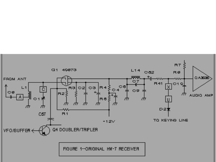
THE ORIGINAL RECEIVER
Figure 1 is the basic receiver chain of the HW-7. Parts designators are those used by Heath. The signal comes from the T/R relay through C6, to the preselector (C1 and L1). It is fed into one gate of Q1, and the other gate gets the VFO signal from 04, the doubler/tripler which follows the VFO buffer. (R1 and R2 set the bias for that gate.) Q1 mixes them and the output passes through an audio filter (L14, C5, C7 and C9) and then into a CA3035 integrated circuit audio amp.
Here are the parts values used in the original receiver.

C1 393 pF 	R1 100K
C2 .05 		R2 56K
C3 100 		R3 470
C4 100 		R4 1500
C5 .22 (.01) 	R5 100
C6 100 (.01) 	R6 1K
C7 .01 		R7 180K
C8 none (.01) 	R41 1K
C9 .22 (.01) 	L1 1.6 uH
C10 .01 	L14 200 mH
C52 2 uf
C57 15 pf
(Note-I have two different HW-7 schematics; in the older one, the capacitor on the left leg of L14 is a pair of .01 caps in parallel, C5 and C6, and the connection from the antenna goes directly to the tap on L1, with no capacitor. The cap on the right leg of L14 is another pair of .01's, C8 and C9.)
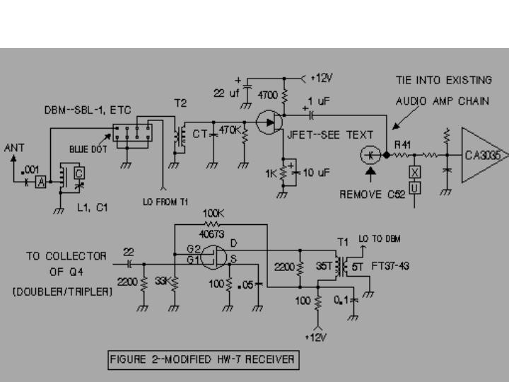
THE KN1H FIX
NOTE: Figure2 shows the modifications made.
The KN1H modification consists of rewiring Q1 into an amplifier for the VFO signal so it can drive a DBM (the MCL SRA-1 in his case, although the SBL-l is just as good, and cheaper) as the local oscillator (LO), and feeding the signal from the preselector into the RF port of the mixer. The audio output (IF port) is then fed into a preamplifier he added, and on to the CA3035. Q1 itself was left in place on the circuit board; some of the surrounding components were changed in value, some new ones added, some traces cut, etc, to turn it into an amplifier.
All of that made things a bit hard to follow, but it did work. It would be much easier if all of the circuitry was built up on a single board from scratch, rather than modifying the HW-7 board. While I haven't actually done that part myself, the diagrams here should make the process much easier and clearer.
PART OF THE ORIGINAL KN1H ARTICLE
"My HW-7 was found at a hamfest several years ago. It was terribly dirty but carried a $15 price tag. So, with a warning from its owner that it didn't receive "too well", I carried it home and plugged it in. Well, the original owner was at least partly right&emdash;it didn't receive at all, or transmit either!
"I pulled out the PNP transistor that was in the oscillator section and replaced it with the FET which belonged there, and in a few days had a working HW-7. The transmitter worked pretty well and on receive I could listen to the VOA, the BBC and our local AM station all at once on 40 meters. I could also listen to 20 meter CW stations on 15 meters. That is, if they were stronger than the ever-present common-mode hum. "This HW-7 was looking less like a bargain all the time, but by now, with $15 and several days invested, I was determined to make a radio out of this thing.
GET A NEW MIXER
"First, the 40673 product detector had to go. The square law characteristics of the dual gate MOSFET make it a wonderful detector of any AM signal that appears at its input. The passive double balanced mixer I put in its place has no such tendencies (due to its balance); it does suffer from conversion loss, the requirement for a high level of local oscillator (LO) injection, and a low impedance output.
"The LO requirement was met by simply reconfiguring the 40673 as a broadband amplifier to boost the LO level going into the DBM. T1 is a broadband transformer with 35 turns on the primary and 5 turns on the secondary, wound on an FT37-43 toroid. This delivers about +5 dBm into the 50 ohm impedance of the DBM-a little less than the optimum +7 dBm, but it works quite well. "The conversion loss and low output impedance problems are both handled by a neat trick first published by PA0SE, Dick Rollema, "Second Thoughts on the Direct Conversion Receiver", Ham Radio, November 1977, pages 44-55. (This article is highly recommended to anyone interested in DC receivers.) The audio output of the DBM is fed directly into a miniature audio transformer with a high turns ratio, which feeds a FET amplifier. The transformer performs several functions all at once. First, it provides a low impedance for the DBM to see, and then it steps the audio voltage up to a high level which improves the FET noise characteristics. The transformer I used is an 8 ohm to 15K ohm unit found in the junk box. It has a 44:1 turns ratio (the square of the turns ratio = impedance ratio), and works well; but an even higher ratio might work better.
A FREE FILTER
"Capacitor CT across the secondary was chosen to resonate the winding at 750 Hz. This cleans up the waveform and gives a 3 dB bandwidth of about 1 KHz. A free audio filter! The value of C will have to be determined experimentally as the secondary inductance of your transformer will undoubtedly be different from mine. My C turned out to be 0.015 uF. [And beware of using a disc ceramic capacitor here&emdash;I did, and it turned out to be an excellent source of microphonics! Many ceramic capacitors exhibit the piezoelectric effect and can generate small voltages when tapped&emdash;and this capacitor is followed by a high gain audio amp. -WA8MCQ]
"Almost any FET will yield good results in this circuit, but some will be better than others of the same type number. One particular 5308 I had gave about 10 dB more gain than its nearest competitor, so it was used here.
"These modifications completely cured the AM breakthrough and common-mode hum problems [see sidebar], even when using an AC power supply. The problem with 20 meter stations breaking through on 15M was helped (but not totally eliminated) by feeding RF to the DBM from the tap on the preselector coil (L1) rather than the top of L1 [as done in the original HW-7 circuit]. With this arrangement, preselector tuning is much sharper and there is probably a closer match to the input impedance of the DBM. Also, C6, originally 100 pF, was changed to 0.001 uF which resulted in a 6 dB signal increase on 40M, but no change on 20 and 15.
"The added portions of this modification were assembled, ugly fashion, on a piece of double-sided PCB which was then bolted to the side wall of the HW-7 chassis. RF and LO interconnections were made with RG-174 mini coax, and +12V is supplied from the ON-OFF switch.
[Description of reworking the original 40673 circuit by changing and removing parts and cutting traces is deleted. While it can be done, it's a bit confusing and hard to follow, and it's probably better to simply build up the circuitry on a separate board. -- WA8MCQ]
"I have found this modification to be extremely worthwhile; the HW-7 is now a thoroughly usable QRP rig with a pleasant sounding receiver. Not bad for a $15 radio) With the hamfest season approaching, let me suggest you keep an eye out for an HW-7. When you have made the modifications described, it may become your favorite rig.
WATCH OUT FOR TRANSFORMER HUM
When I modified my HW-7 according to Johns instructions, I used whatever audio transformer was handy and small enough to fit. The turns ratio wasn't as large as he used, but it was adequate. (I believe it was 8 to 2000 ohms.) There is one problem with using the transformer; if you put the modified rig too close to a power supply, hum may be induced in the audio of the HW-7, coupling magnetically between it and the supplys transformer. The solution is simple; reorient the power supply, or move it farther away from the rig. ("Doctor, it hurts when I do this." "Well then, don't DO that!")
ROOM FOR EXPERIMENTATION
This isn't necessarily the best audio preamplifier circuit, but it does work. You might want to experiment with something else, such as the circuit used in the W7EL Optimized QRP Transceiver (August 1980 QST and the second printing--not first-of QRP Classics from ARRL). You might also want to experiment with a different audio amp, such as an LM-386, LM-380, etc, and perhaps insert a filter. This is not the only way to fix an HW-7 receiver section, but gives you the basic idea. There is lots of room in the HW-7 for modifications.
If you see an HW-7 at a "good" price, don't pass it up because of bad things you may have heard about its receiver. It CAN be fixed!
COMMON MODE HUM
What is common-mode hum? That was one of the many shortcomings of early DC receivers, also known as tunable hum. When operating on an AC power supply, you could tune the preselector to peak signals, and at the same time hum would start coming through. It is now generally accepted that the cause of this is VFO energy leaking out and getting back to the diodes in the power supply, being modulated with 60 Hz AC, reradiated and picked up by the receiver along with desired signals. Some cures were mentioned above--do away with the AC power supply completely, or put a choke between it and the receiver to keep the VFO energy from getting to the diodes, or bypass each diode in the rectifier with a capacitor so the signal couldn't be modulated.
-- WA8MCQ
Use Your Browsers BACK Key to Return to the Previous Page