In ham radio, antennas are one of the most
important factor in successful communication. The best and most expensive
radio available isn't going to perform unless you use an efficient antenna.
My belief is that nothing is better than a separate antenna for each band
you want to operate on. Antennas don't have to be complicated or difficult.
It takes some understanding of how they work and the formulas for cutting
wires at the proper length. But antennas can be very forgiving about where
you put them, how high etc. Many people do ok with a simple dipole antenna
in there attic. Here we have many trees in the yard and they are great
for hanging my wire antennas. Here's one of my 1st experiments. Its basically
a 2 element quad design in a rough delta shape. The two elements
are cut for the desired frequency and then separately hung up in the tree
branches.
This quad has only two wires to cut. The first
one is called the driven element. That's the wire that is attached to the
coax feed line. To find the length of a driven element for the 15M ham
band use this formula. DE=1005/mHz.
For example. I operate 15 meters around 21.060mHz,
so 1005/21.060 = 47.7 feet. So cut a wire about 48 feet long.
The last element is the reflector. Use this
formula for that. 1030/mHz. Our 21.060mHz reflector should be cut at 48.9',
so lets cut it at 49' to be safe. The driven element is hung in the tree
branches facing the direction you want most to talk. I aimed my tree quad
NE/SW and could use the front to Europe, and off the back talked to Australia.
The reflector is hung behind the driven element to reflect any RF back
the way it came, so most of your signal is heading forward. The exact delta
angles don't need to be perfectly aligned to each other. We are using tree
branches, and have to accept the shape we end up with.
The space between the two elements isn't critical
in my experience. Get them at least 4' apart, and make the space as even
as you can at all three points of each delta point. I would think that
5 or 6' separation is about as far as you want them.
The most important part is the tune up procedure.
First carefully and very briefly hit the CW key and check the SWR. You
should see a fairly high SWR reading, but hopefully not a dangerous one.
Start with the driven element and trim one or two inches off one end. Re-attach
the wire and test the SWR reading again. Hopefully this improved the reading.
Take off another couple inches and re-test. If you are seeing big improvements
keep cutting and testing until progress slows or stops.
Its then time for the next element. The reflector
will be easier than the DE! Write down the readings so you don't get lost,
and trim the reflector, re-attach and re-test. In this process you are
matching several factors, wire length, separation of the two elements,
and things I will call gremlins. Branches, how the coax is laid out, and
other things we have little control over.
Naturally as you transmit a test signal on
the air, you need to listen and be sure you don't interfere with anyone,
and send your callsign to keep it all legal.
My Tree Quad antenna

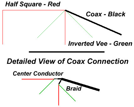
The Square Vee antenna
I started working with the half square antenna afew years ago and have one on 30M and another for 20M. They work very well for being so low. Both are only at around 25'. Stretched between Oak trees in the front yard. They work the same as a pair of phased vertical antennas, and have good low angle RF take off patterns. Unlike verticals they don't need radials at all.
With these two wire antennas in the front yard
I was wondering how I was going to hang any other bands out there. Then
I got the idea of attaching an inverted Vee dipole from the feed point
of my half squares. I tried it and it seems to work really well. It gets
another band covered and shares the same coax as the half square.
Half square Wire Length
Band Horizontal Vertical
10m 17'
09'
12m 20'
10'
15m 24'
12'
17m 28'
14'
20m 35'
18'
30m 49'
25'
40m 70'
35'
75m 128'
64'
80m 140'
70'
Remember, you need two lengths of the vertical wire for your antenna.
The regular formula for the inverted vee can be used. The formula is: Freq / 468 . To use this formula, take the center of your desired frequency range, in MHz, and divide that by 468. This will give you the total length of the two halves of the vee in feet. Divide that number in half to get the length of each side of the vee.
Back to index - ![]()