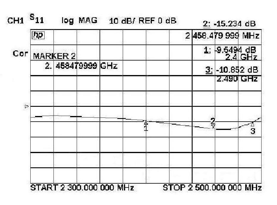
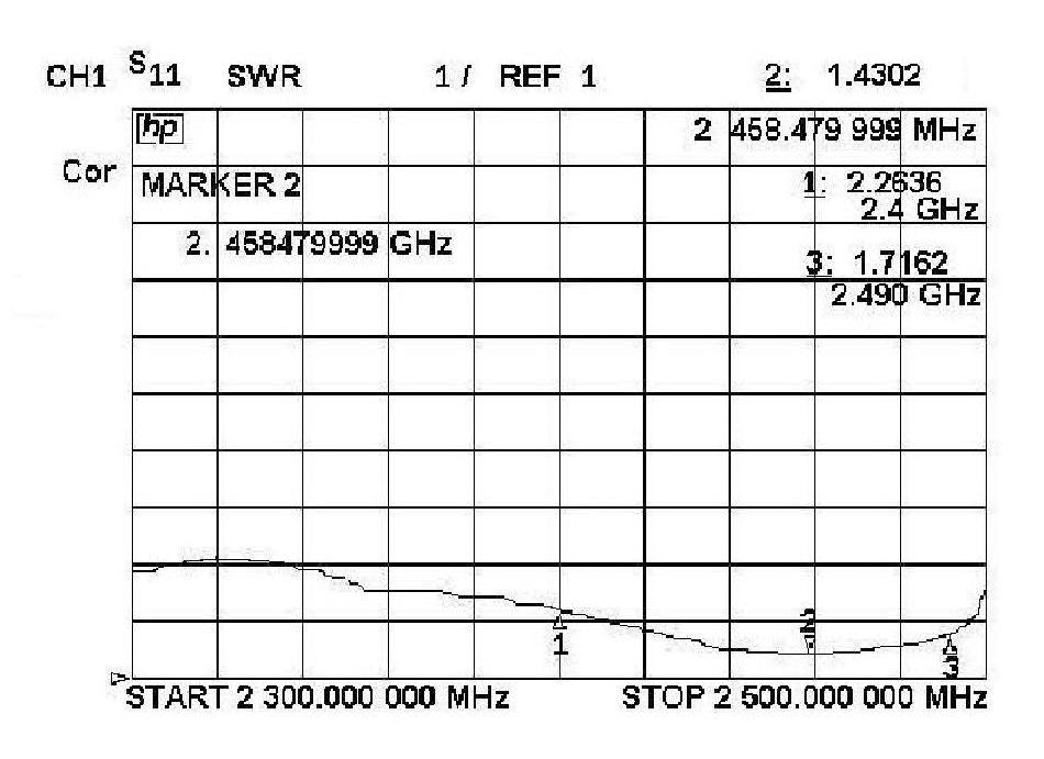
 "Microwave Mike", N7QYH used a Hewlett Packard 8353B network analyser with an S-Parameter test set to plot the return loss, or SWR for the feed.
A "Cheap & Easy" 2.4GHz Feed
By James H. Wolfe, KI7CX - EMAIL
[email protected]When the AATV group in Phoenix added a 2.4 GHz FM input to the ATV repeater, it provided hams a way to get on ATV "cheap and easy". The 2.4 GHz Wavecomä types of audio/video transmitter/receiver sets are certainly a reasonably priced unit for ATV use. The transmitters are easily modified for more power, and kits and add-ons are showing up to boost the power even more. The only thing that seemed to be lacking was an inexpensive antenna.
We know that when frequencies get above about 900 MHz, a parabolic dish is the real ticket for maximum gain. At 2.4 GHz, it is easy to get 20 to 25 dbi or more with a dish & feed that is manageable in size. Occasionally I have seen 16" to 20" inch obsolete HBOä type dishes at hamfest’s and recently the larger Primestarä and other digital TV dishes are showing up.
We also know that a parabolic dish is not frequency dependent. It is the feed for the dish that must be constructed for a specific frequency range. We also found that we could home brew a feed using common materials.
Here is a "cheap and easy" circular waveguide feed that can be built for the 2.4 GHz ATV band. While it is not an ultimate ATV DX antenna, it is simple to construct, affordable, broadbanded and has about 10dbi gain right out of the can!
Required Materials
Construction
Solder the open ends of the two cans together to form a 7.15" tall cylinder. After soldering the cans together simply use a can-opener to remove the end of the bean can.
Measure 1.82" (46.21mm or 1-13/32") from the closed end of the can. (Measure inside the can to the open end and transfer this measurement to the outside). This is the center of the probe, (chassis connector). Drill a hole large enough for the insulated portion of the chassis connector to pass through.
Solder a piece of 3/32" tube or #10 wire to the center conductor of the chassis connector, creating a probe 1.125" or 1-1/8" long. Solder the chassis connector in place. The body of the chassis connector remains outside the can. The probe extends into the can and remains isolated from it. (This is a driven element, or a waveguide quarter wave antenna at 2.4 GHz.) We now have a complete circular waveguide feed that can be used as a stand-alone antenna.
The Scalar Ring
While an open ended circular waveguide makes a simple feed for a parabolic dish, the illumination pattern is not as ideal as it first appears. We have too much energy in the center and too little at the edge. A satellite television antenna feed uses a unit made up of a series of shallow cavity rings surrounding the waveguide. This is known as a Chaparralä feed and it is so named for the originator. The Chaparral feed alters the illumination pattern and improves the efficiency of the feed. This type of feed is also well suited to the small HBO dishes with f/D in the range of 0.35 to 0.45. When scaled to our 2.4 GHz feed, the first of these rings is 5" in Diameter and 1-1/2" deep. For a larger dish application, additional concentric rings would be used. We used only one ring to avoid blocking too much of our small center fed dish.
Cut the Candy or Cookie tin down to a 1.5" depth to create the scalar ring.
Draw two concentric target circles on the bottom of this shallow can, the first a 2" diameter bull’s-eye and the second 3.25" diameter.
Cut out the 2" bull’s-eye to make a hole in the bottom center of the can
Cut from the edge of the 2" hole to slightly past the 3.25" circle a series of ¼" wide ‘teeth’ all the way around.
Bend these teeth at the 3.25" circle away from the bottom of the can 90 degrees. This forms the scalar ring for the feed.
Slip the scalar ring onto the feed. This will need to be adjusted in or out for maximum gain. After fine-tuning, the scalar ring should be fastened or soldered in place.
Mounting
The position of the scalar ring is relative to the f/D ratio, or focal length to Diameter ratio of the dish. The focal length or position of the feed horn is easy to calculate. Here is a quick primer to determine the characteristics of a round parabolic dish.¹ The focal length is simply the Diameter squared and divided by sixteen times the depth at the center. To determine the f/D ratio simply divide the focal length by the dish diameter. Here are two examples. One of my HBO dishes is 18" in diameter. With a straight edge across the dish, it measures 2.5" deep at the center. (fl=D²/16d) The focal length is 18* 18=324, 16* 2.5=40, 324/40 or 8.1", and the f/D ratio is 8.1"/18", or 0.45. Another dish is 20"x 3.5" which has a f/D of 0.35 and a focal length of 7.14". In these examples the 18" dish would have the mouth of the feed positioned approximately 7-3/4" from the center of the dish. (The feed point is slightly inside the open end of the waveguide.)
The 20" dish would have the feed mounted approximately 6-3/4" from the center of the dish. The position of the scalar ring will differ between the two dishes due to the difference in f/D ratio. The position will also have a very slight variation between transmit and receive.
To use the scalar ring and the feed horn as an antenna, (no dish), position the back of the scalar ring approximately 1" from the mouth. This will place the outer rim of the scalar ring slightly forward of the open end of the feed. Fine-tune the position from this point. When mounting the feed on a dish, peak the feed horn, then add and adjust the scalar ring.
Note: Polarisation is determined by the probe orientation. I.e.: Horizontal probe is horizontally polarised and a vertical probe is vertically polarised.
"Microwave Mike", N7QYH used a Hewlett Packard 8353B network analyser with an S-Parameter test set to plot the return loss, or SWR for the feed.

A completed feed ready to be mounted on a small HBO dish. The center support is made from a ¾" PVC pipe with a wooden dowel inserted in it for additional support. A PVC cap fitting is glued onto the pipe and screwed to the center of the closed end. The "bug-shield" is a cover from an electrical tape container which was cut out and slipped over the center support before it was glued in place. The "bug-shield" also serves as a support for the open end of the feed.
 This feed is mounted with a PVC to male threaded adapter at the center of the dish. The male adapter has been drilled out to allow the PVC to slip in and out for final adjustment or to allow the feed to be used on another dish
. Dale – KA7ATV spent $5 at a local hamfest for this dish, and another 25¢ at a yard sale for an empty 5" Diameter cashew’ can. The original feed was removed and a new mount was fashioned from scrap aluminium. That is "cheap and easy."
With a set of Wavecom’s, and a polaplexer² feed, operation of full duplex ATV with another station having the same set-up, seems possible. The Wavecom has two of the stock frequencies in the ham band. Each station can transmit on the other stations receive frequency. Just think; full duplex and no repeater! So satisfy that craving for tuna and beans for lunch. Hunt up the big soldering iron, and you could be on ATV before supper.
73.. de KI7CX – Jim, "See you on the radio!"
NOTES
Note 1: Paul Wade - W1GHZ has a website that contains a wealth of technical information related to microwaves including information on determining feed points for offset dishes. His web page can be found at,
www.tiac.net/users/wade.Note 2: Polaplexer Design and Construction, The Polaplexer Revisited by Ed Munn – W6OYJ
Parabolic Reflector Antennas and Feeds by Dick Turrin - W2IMU, ARRL UHF/MICROWAVE EXPERIMENTER’S MANUAL
Another excellent source of information on this subject is DUBUS articles on line,
www.mrs.bt.co.uk/dubus