MICROWAVE OVEN TRANSFORMER (MOT)
P. Wokoun (9/2003)
(When you click on a picture, return by using your browser's back button.)
These transformers power 600-1200 watt microwave ovens but are they suitable for hobby or amateur use?
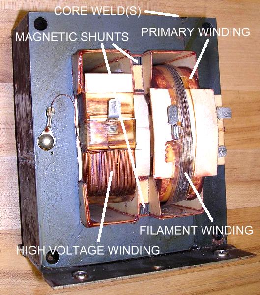
The transformers are large and heavy, indicative of a high power capability. They consist of a primary winding normally about 117 volts AC, a high voltage winding of about 2000 volts and a filament winding about 3 volts.
Physically, the one I had was different in its core arrangement from what I normally see in power transformers. A conventional core consists of alternating stacked EI laminations insulated from each other by a varnish coating. I learned insulating the laminations was to keep core loses to a minimum. The oven transformer has fully stacked EI laminations butted together and welded across the EI junctions to hold it together. I was curious to see how this welding the laminations together related to core losses. It definitely made disassembly impossible unless you wanted to grind away the weld. Size of the center core is 3.5 square inches and the end pieces are 1.7 square inches.
The transformer also had a couple stacks of laminations wedged between the center core and the end pieces between the primary and high voltage windings (magnetic shunts?). (CLICK FOR PICTURE) These stacks were not directly against the EI core but had some appreciable air gaps (actually paper gaps). I have read that these have something to do with limiting fault currents through the magnetron. I don't know for sure. They decreased the no-load core loss by about 8% but had negligible effect throughout the normal operating region. I elected to premanently remove them to give a larger winding area.
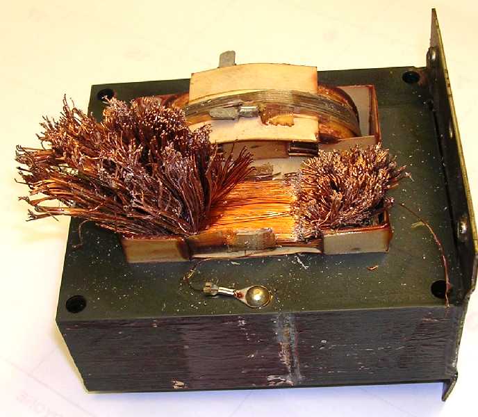
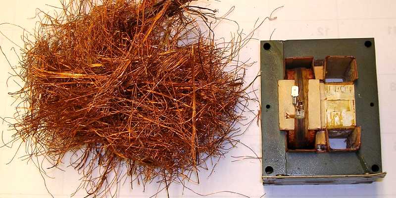
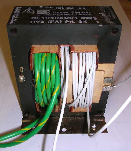
Since I was interested in a low voltage, high current application, removal of the high voltage winding appeared to offer a fairly large area around the core to wind an appropriate winding. The first step removed the paper exposing the high voltage coil. Being careful not to nick any of the primary windings, the HV sinding was chiseled through using a small (1/8") screwdriver and pulling the wires away from the cut. (CLICK FOR PICTURE) This was repeated on each side of the transformer. Eventually you get to a point where you can pull the wire pieces out of the core. It took me about 1-1/2 hour to cut and remove the entire winding. Ingenuity and persistence can pay off here. (CLICK FOR PICTURE)
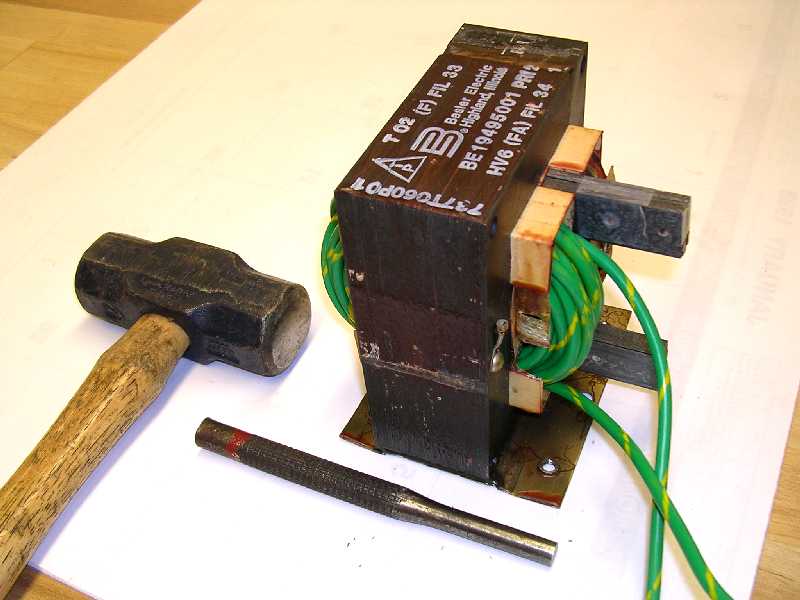
After the high voltage winding was removed from the core, the transformer was supported on two pieces of wood (CLICK FOR PICTURE) and the two magnetic shunt pieces were driven out using a 3/8" drive pin punch and big hammer. (CLICK FOR PICTURE) This is where a few well-placed, heavy blows work better than a lot of little hammering. Once the varnished joints are broken they will knock right out. Again take care not to damage the primary winding. I had a piece of #10 insulated wire which I used to wind a test winding in the high voltage winding space. I was able to wind 16 turns on the core before running out of space and wire.
The first test was to run various input voltages to the primary and monitor the input current. The results are plotted in Figure 1.
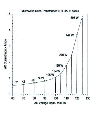
FIGURE 1
Interestingly, the core loss shows a steady rise up to about 105 volts input from which it starts rising rapidly. It looks like the core is raching saturation at about 110 volts. Monitoring the voltage across my 16-turn test coil, however, shows its voltage increasing very linearly to over 125 volts input as shown in Figure 2.
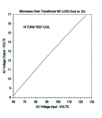
FIGURE 2
This shows the core is not saturating out. If it were the output voltage would show a flattening at the onset. The waveform of the secondary voltage was sinusoidal with no apparent distortion being introduced. This was the same for both unloaded and loaded conditions.
I grabbed a comparably sized standard power transformer to see how its core losses compared to this MOT. Figure 3 shows this other transformer's no load losses.
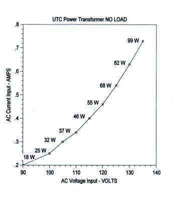
FIGURE 3
Comparing these values with those shown in Figure 1 you can see the MOT has over 4 times the core loss at 105 line volts, 6 times at 115 line volts, and almost 9 times at 125 line volts. This MOT is definitely a different breed of power transformer.
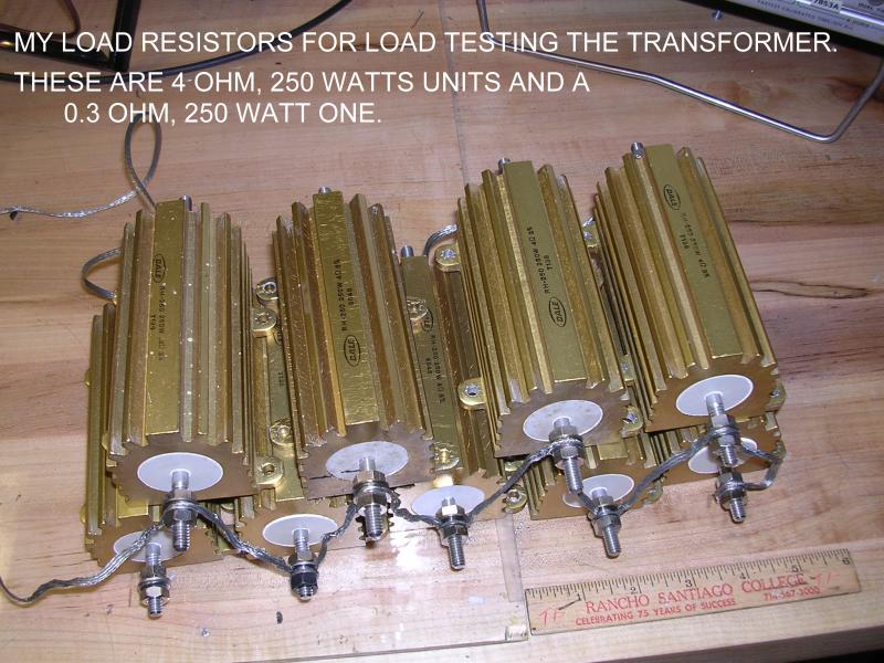
Next I applied various loads to the test coil at different line input voltages. (CLICK FOR PICTURE) Figure 4 is the graph of the results.
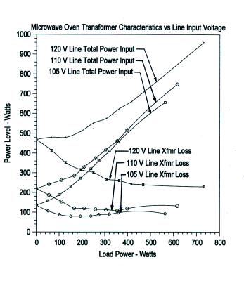
FIGURE 4
This figure actually consists of 6 plots. Three plots start on the Y-axis and rise towards the upper right corner. These are the total power input curves as read on the input line voltage and current meters. The other three plots start at the Y-axis and slope downward towards the lower right corner. These are the transformer core losses at the different line voltages. They are the total power input curves which have the load power subtracted out. It's interesting that the core losses actually decrease with increasing load. Here we have a transformer that runs more efficiently at full load than no load. But of course, a microwave oven is designed to run loaded, not unloaded!
What concerned me a little was the large increase in transformer loss from 110 to 120 line voltage, an increase from about 220 watts to 470 watts at no load. This transformer is going to run hot when lightly loaded with nominal line input. Then I ran some temperature tests just to see how hot it would actually get with different line input voltages and no load. Nothing fancy here, I just had the transformer sitting uncovered on an insulated pad. The thermometer was held hard against the core with some thermocompound to improve the heat transfer. Room ambient was fairly constant at 68 degrees fahrenheit. Testing at each line input voltage continued until the core temperature stabilized somewhat over a half-hour period. Figure 5 is the result of this temperature testing. Sure enough, the transformer ran H*O*T! Incidentally, this MOT was located in its oven directly in front of an exhaust fan that would have kept its temperature down.
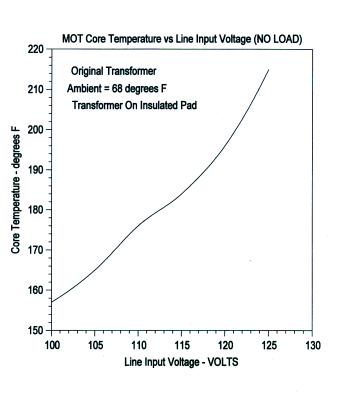
FIGURE 5
Figure 6 shows what the volts-per-turn at different power levels is for this transformer with a line voltage of 105 volts AC.
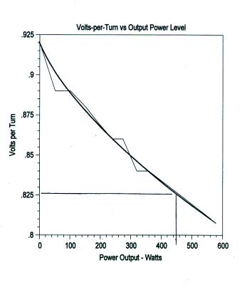
FIGURE 6
I was thinking that I really disn't want to run this transformer with more than 105-110 volts on the primary to keep the core at a reasonable temperature. What I needed were additional primary turns to keep the nominal line input voltage on the original primary to only 110 volts maximum. If the input line voltage was 125 volts and I only wanted 110 volts on the primary winding, then I needed to drop 15 volts. From Figure 4 the volts-per-turn at a power level about 450 watts which I was designing for is 0.825 volts per turn. To drop 15 volts I would need 18 additional turns. I wound an 18-turn coil over the existing primary and in the spaces where the two magnetic shunts were located. I wired it in series with the primary winding, phased to give the minimum voltage on the 16-turn test coil. (CLICK FOR PICTURE) Almost perfect, at no load a 125 volt input resulted in about 109 volts appearing across the original primary winding.
Figure 4 data was repeated with this additional winding in the primary and Figure 7 is the result.
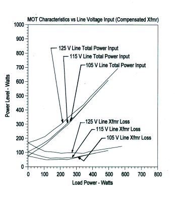
FIGURE 7
It now shows considerably less variance between the different line input voltages. Maximum core loss at 125 volts input was now only 170 watts compared to over 600 watts previously.
A new volts-per-turn graph was ploted and shown in Figure 8.
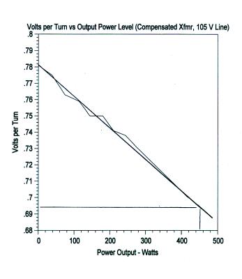
FIGURE 8
It shows my volts-per-turn for this transformer has now dropped from 0.825 to 0.694.
What I have done is exchanged a very hot running transformer for one that now requires more turns for the same output. For example, a 20 volt winding before would have required 24 turns; now it requires 29 turns.
The question now is: Is there enough room on the core for the additional turns?
I'm also curious to know if other microwave oven transformers will run as hot as this one. I'll keep my eyes open for another one to 'check out'.
Stay tuned for further investigations with this transformer as time permits.

