 Here's a little mod you can do to this item
available from several sources on ebay that will increase its battery life more
than 200 times from its received condition.
Here's a little mod you can do to this item
available from several sources on ebay that will increase its battery life more
than 200 times from its received condition. NOAH'S FLOOD ALARM MOD (P. Wokoun, 12/2008)
Here's a little mod you can do to this item
available from several sources on ebay that will increase its battery life more
than 200 times from its received condition.
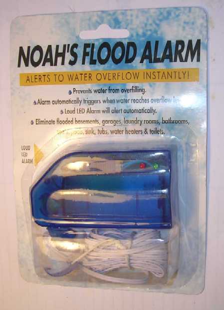
After our latest hassle with water under the sink undetected until there was a LOT of it, I decided now was the time to put some water sensor under there so I would know when water started showing up.
Searching on the internet I found this product generally available on ebay for under $10. So I ordered a couple to 'check them out'.
I found the alarms sensitive enough. They use two AA batteries. I measured the current from them at 10 mA when monitoring and 30 mA when alarming. This results in a battery life on only 8 days when continuously monitoring, really unsatisfactory. Their instructions say to switch off when not in use to save battery life. So it seems they weren't intended for continuous monitoring.
They have a red 'alarm' led and a green 'monitor' led. Opening up the unit to take some measurements I found almost the whole 10 mA of current during monitoring was used just to light the green led. Disconnecting the green led dropped the current to only 50 microamperes! This calculates to a battery life of almost 4-1/2 years. Since the unit will be mounted under the sink where not visible, I didn't need a 'monitor' led.
So now I have my battery operated water sensor with a very long battery life. By the way, the alarm is quite loud enough to hear in a home setting from under the sink.
My next task is how to improve on its water sensor probe.
To see the mods keep reading. To accomplish them you will only need a very small phillips screwdriver (#0 or 00) and a small pair of wire cutters. A small jewlers screwdriver set also worked almost better then the small phillips screwdriver.
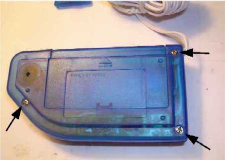
To open up the unit, remove the battery compartment cover, then remove the three screws shown here. Lift the rear cover off. The noise alarm will remain attached to the rear cover connected to everything else with a couple small wires.
What you see should look like this.
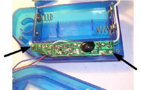
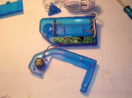
The next step will involve removing the small printed circuit board since what we need to get at is on the other side. Remove the two small screws shown here. Then lift the printed circuit board straight up maybe a 1/4 inch to clear the switch and led recesses. Then rotate the printed circuit board around its right side. We don't need to remove the wires going to the battery and the sensor on the right side.
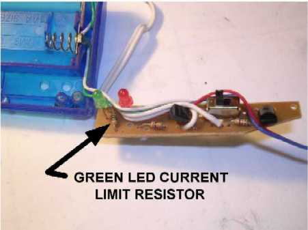
This is the printed circuit board removed from the case. The green led current limiting resistor is between the green and red leds. What we are going to do is cut one of the leads on this resistor.
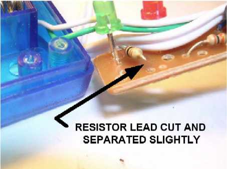
Taking the small wire cutters we cut one end of the green led current limiting resistor and separate the two ends slightly. Now we just reverse all the steps and put the unit back together again.
Replace the printed circuit board insuring the green and red leds go into their recesses and the slider on the front engages the slider switch. Everything should just go together if the switches weren't moved. Put the board's 2 screws back in.
Dress the alarm, battery, and sensor wires; then replace the rear cover. Then put its 3 screws back in. Easy, just work slow and carefully.
![]()
![]()