RADIO SHACK MTA-20 (21-527)
DIGITAL POWER / SWR METER:
A MOD TO IMPROVE VIEWING
by P. Wokoun, KH6GRT
January, 2018
This item is a very useful and handy combination power and swr digital meter. It is probably one of the better Radio Shack items I have come across. It uses a liquid crystal display which is backlit by 4 orange LEDs. For me this meter was getting increasingly more difficult to see. My mod consists of replacing those orange LEDs with white LEDs which increases the contrast with the display. I neglected to take any pictures of my meter before I modified it but this is how it looked using a general picture off the internet:
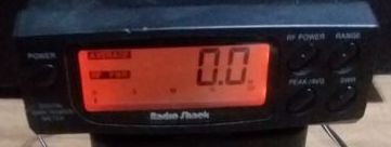
The meter now looks like this so you be the judge which is easier to read:

Here's a partial schematic of the meter showing what's involved in this mod:
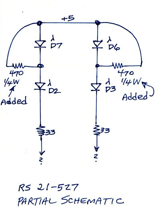
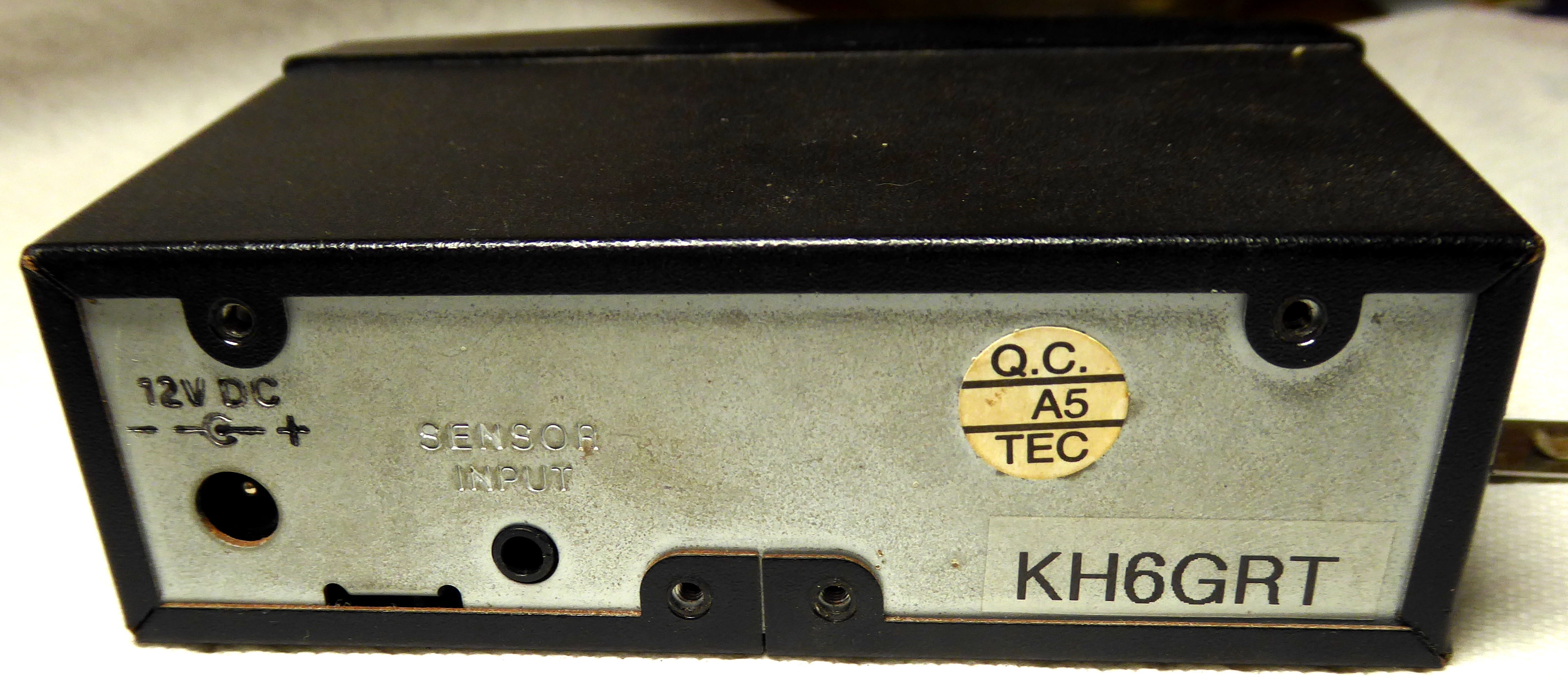
The meter operates from a 12 volt DC supply which is dropped down to a regulated 5 volts. The original orange LEDs are arranged in a pair of two LEDs in series. The 5 volt supply is adequate to power two of the orange LEDs in series. However, the operating voltage for white LEDs is higher and a 5 volt supply is inadequate for a pair in series. So what I have done is just use two LEDs on opposite sides of the display with current limiting resistors to the 5 volt supply. Two white LEDs are sufficient for enough backlight. When all four orange LEDs are removed, just two white LEDs need to be installed, D2 and D3. D6 and D7 don't need to be there. The nomenclature D2, D3, etc can be read off the printing on the printed circuit board.
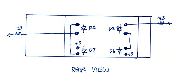
Here is the LEDs orientation and location on the pc board as seen from the backside.
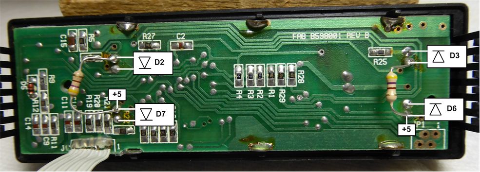
Here is the pc board with the actual solder pads annotated. The 470 ohm, 1/4 watt resistors are also shown connected to the appropriate pads. Again D6 and D7 don't need to be installed. Also increase the resistor for less light, decrease slightly for more light.

There is not a lot of room where the LEDs go. The original orange ones are a flat pack rather than the 'bullet point' style. To minimize the LED protrusion I ground the front part of the LED away on a grinding wheel, stopping short of the internal structure. Here's a good view of one. I left the front rough from the grinding wheel to give a more diffused light. I could not locate white LEDs in the original style package.

This is how my white LEDs ended up protruding which was not enough to cause problems when reinstalling the display.
So what's involved with getting this meter open:
First, remove the four phillips head screws from the rear of the meter. Then slide the outer case off.

Next, remove the single phillips head screw from the small pc board attached to the rear panel. Just let it hang loose for now. Don't flex that ribbon cable too much, the conductors can break.
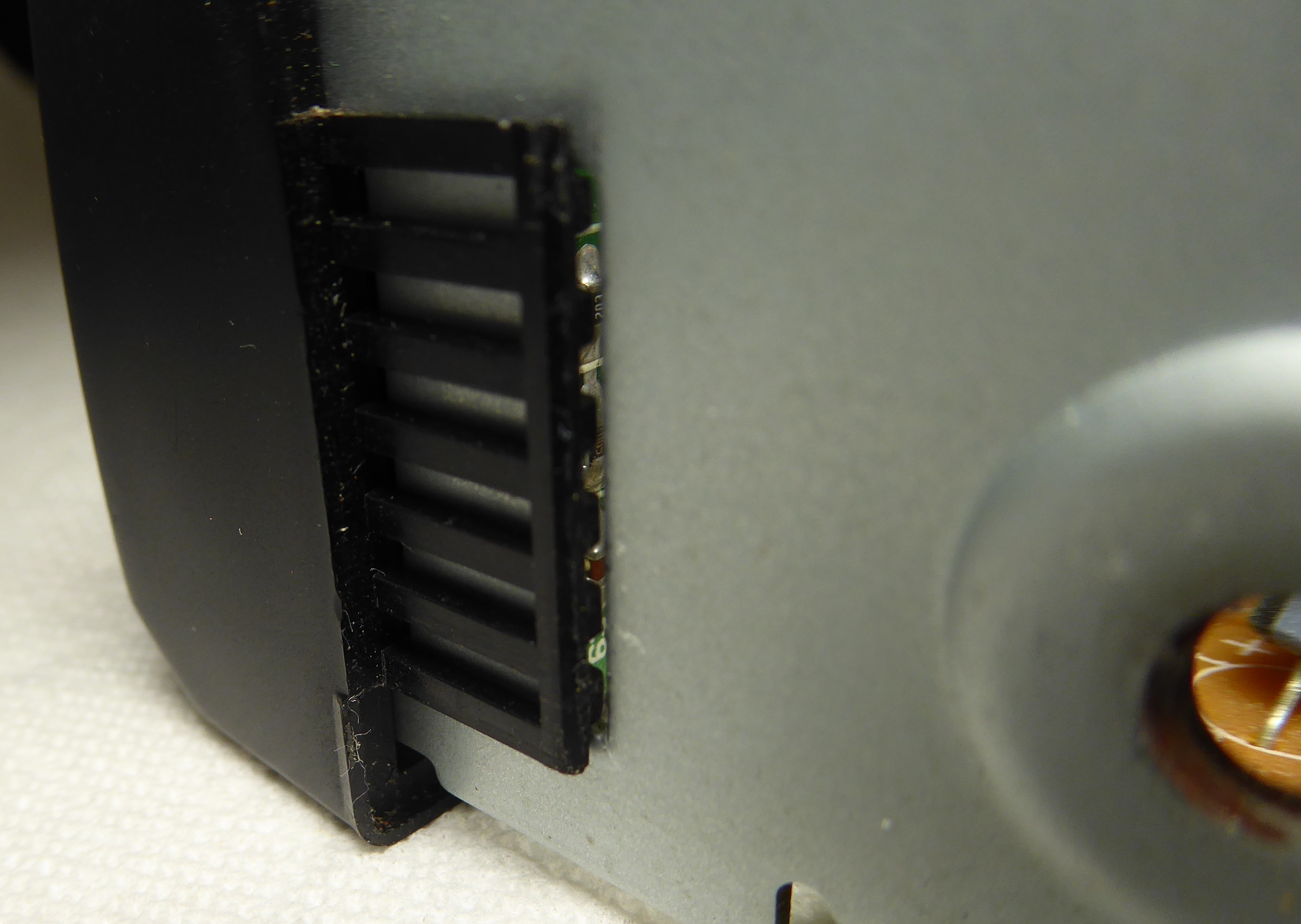
That u-shaped bracket is held to the front panel by a 'grabber' piece from the front panel sitting in a cutout on the bracket. That 'grabber' needs to be pried slightly away from the bracket while the bracket is pulled back slightly from the front panel. When one side is released, go do the other side before pulling completely away from the front panel. You might have to go back and forth a few times. Do not bend the 'grabbers' too much or they'll break off.

I had a small metal scale handy which was able to lift the 'grabber' easily. A small knife edge would probably work fine, too. When both 'grabbers' are free from their cutouts slide the u-shaped bracket out of the front panel. I just let that small pc board hang loose.
 The
next step is to remove the pc board from the front panel. My suggestion is to
keep the front panel pointed downward when removing the pc board. The switch
buttons seem to be different sizes and matched to their positions. When mine
all fell out I had a devil of a time getting them to all operate smoothly again.
So after removing the two phillips screws from the pc board, pull it straight
up keeping these switch pieces where they are. Once you have the pc board in-hand
you can see the LEDs and what's involved in this mod.
The
next step is to remove the pc board from the front panel. My suggestion is to
keep the front panel pointed downward when removing the pc board. The switch
buttons seem to be different sizes and matched to their positions. When mine
all fell out I had a devil of a time getting them to all operate smoothly again.
So after removing the two phillips screws from the pc board, pull it straight
up keeping these switch pieces where they are. Once you have the pc board in-hand
you can see the LEDs and what's involved in this mod.
LED orientation from the front:

I should say a few words about removing the original orange LEDs. The solder pads are close together and you should use a small 1/16 inch iron tip. I did use a 1/8 inch tip but had to be careful and quick. A solder sucker or desoldering braid is a must. The pc board is double sided and if too much heat is used the pads can be lifted or removed from the board. My philosophy is higher heat + quick time is better than lower heat + longer time. I use a variac to control the heat on my iron but a good soldering station will make the job easier. Install the LEDs with the correct orientation: the long lead is usually the anode. The white LEDs used here are the small T-1 size. I can't give you an exact replacement number because the white ones I used came from a general purpose kit where I bought an assortment of 200 LEDs for about $5. You can get these kits on ebay; they come with red, blue, white, orange, and green LEDs in both T-1 and T-1 3/4 sizes with free shipping from China.

