SUPERADIO AUXILIARY INPUT MOD
This is a mod I added to my superadio so that I could listen to various sources such as MP3 players or computers. Since the superadio is not a stereo radio it combines any left and right channel audio into a single mono channel. Its main function for me: to listen to baseball games over the internet and not have to use those tiny, tinny sounding speakers on my laptop. The volume and tone controls still function as normal.
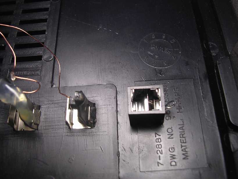
My superadio is one of the last GE: model 7-2887B. I have not investigated whether this mod will work on the other models but I expect it should. The pictures and parts locations may vary.
The work involved is not too difficult; you have to be able to handle a soldering iron with a small tip and not be a complete klutz. After all, you're going to be working among some small and fragile parts.
Here's the list of items you should have on-hand:
1. Soldering iron with a 1/8-inch chisel tip maximum, or a 1/16-inch tip preferred. I use a 45 watt heating element: harder on the tips but gives you a little more heat. I have found a higher temperature does a better job because you don't need as much time heating the area as a lower wattage iron would need; less heat actually flows to the adjacent components. Higher heat and less time vs lower heat and longer time--go with the former. I actually run my iron from a variac where I can dial up any heat I want.
2. Small diameter rosin-core solder.
3. 15/64" (or 1/4") drill.
4. 1/8" open-circuit stereo jack. Get a good one and avoid future problems.
5. Small diameter (1/8") insulated shielded wire about 16" long.
6. 2-each 47,000 ohm 1/4-watt resistors (yellow-violet-orange-gold).
7. Phillips #2 screwdriver.
8. Long nose pliers, maybe.
9. Quart size zip lock bag.
10. Patience.
Opening the Radio:
1. Pull out the batteries. Put the battery cover out of the way.
2. Remove the knobs. The volume, bass, and treble knobs are pulled straight off. They just have a straight knurled shaft. One of mine was really tight and you can use pliers or teeth. The tuning dial is also pulled straight off. Put them all into the zip lock bag so you don't lose any.
3. The back is held on by 7 screws. Six are around the outside in deep recesses and one is in the battery compartment. The six are long buggers and they may not come out so just leave them in their recess hole. Those that do come out can go into the zip lock bag. A phillips #2 tip screwdriver in good condition fits them perfectly.
4. With the 7 screws out, start pulling the back off from the bottom working your way towards the top; the on/off switch needs to move downward and out. Try pushing the power switch ON to keep it recessed a little more. Work slowly and carefully, not forcing anything. Remember the patience! All of sudden it kind of just pops open. When it does pop open the front with the speaker will remain attached by a couple wires. I was able to do everything leaving the speaker attached and just moving things around.
5. You can also remove the chromed pieces on the slider switches and stick them in the zip lock bag now. They'll probably fall off for you anyway.
Positioning the Radio:
I found it easiest to position the circuit board towards you with the speaker off to your left.
Cautions you want to be aware of or they'll cause you a bunch of grief:
1. There is a bunch of fine wires from the antenna rod behind the dial. You don't want to break any of them. I just stayed away from them.
2. You don't want to get your soldering iron anywhere near that nylon string that moves the dial indicator. It will melt immediately and you'll have a PAINFUL restringing repair to go thru.
3. The trick in doing these mods is to quickly tack solder to small component leads so we don't have to remove the circuit board to gain access to the circuit traces below. So when soldering to the leads DO NOT pull the leads up from the circuit board. Even if the leads get hot enough to melt the solder below, if the leads stay intact the solder will just harden up and no one will be the wiser. But normally with a nicely tinned soldering tip you won't need a lot of time heating up anything.
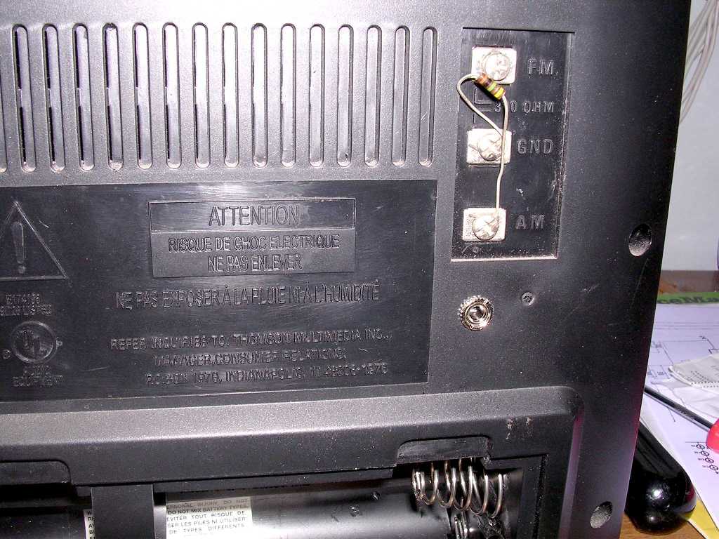
Mount the jack first:
I put my jack about 7/8-inch below the lowest antenna screw on the back. Drill the hole and mount it; what more can I say. I used a 15/64-inch drill but a 1/4-inch will also normally work for the 1/8-inch jacks. The threaded stem on my jack could have been longer but I think I got about 3 threads or so into the nut which tightened up without strippping out.
Locate the solder points:
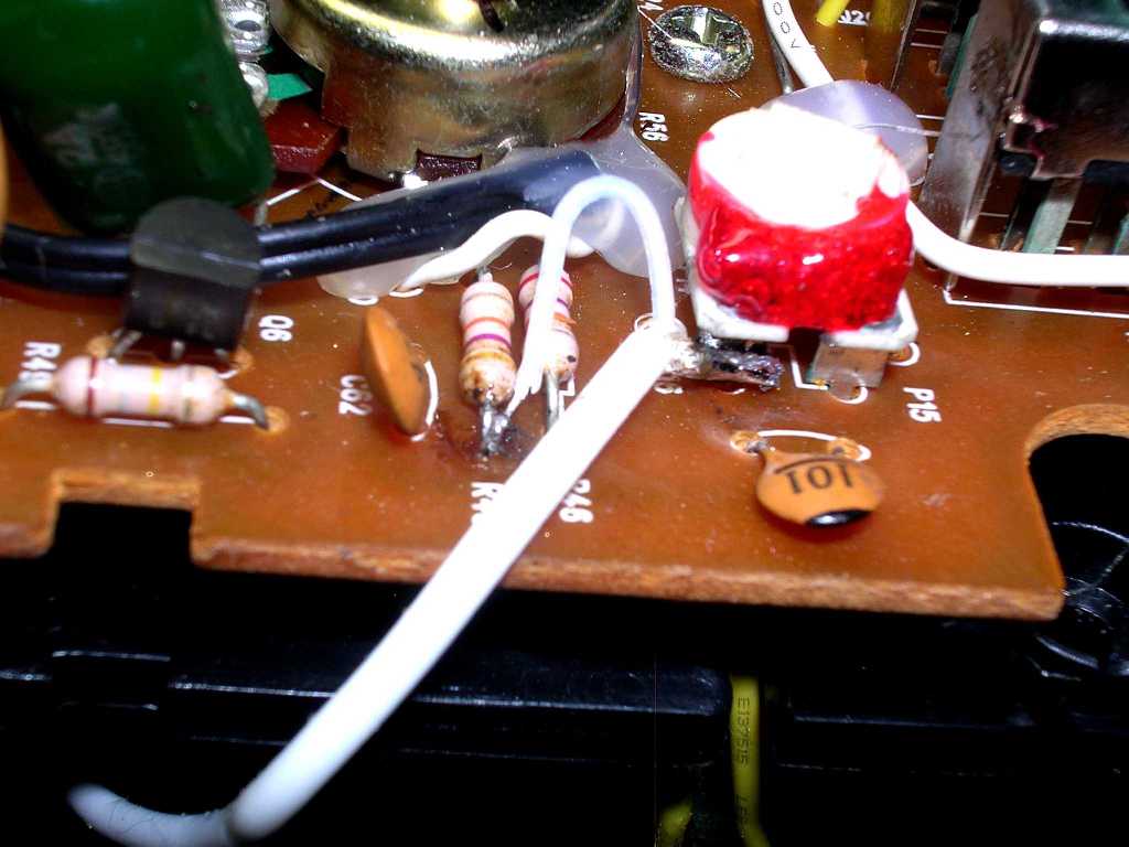
Look at the picture below and you should have no trouble finding the component leads we are going to be working with.
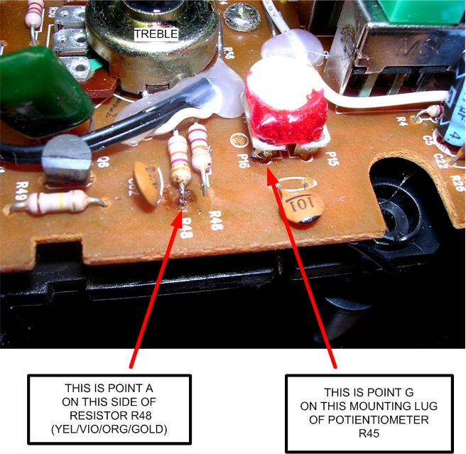
Point A is just in front of the treble control (the upper potientiometer) on the outboard side of resistor R48 (47K, 5%) and Point G is the left mounting lug of potientiometer R45 to the right of the treble control.
Heat up the soldering iron and melt a small amount of solder onto the leads like the picture above shows.
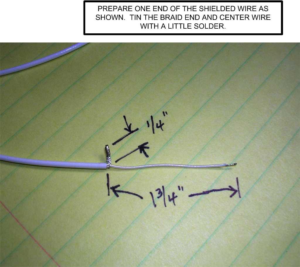
Prepare the shielded wire:
Total length of the shielded wire is about 16-inches. Prep the end like the picture below shows EXCEPT make the center conductor only about 1-inch instead of 1-3/4-inch. The shield end can be left about 3/4-inch.
Solder the shielded wire to the circuit board:
Now solder the prepared end of the shielded cable to the points A and G on the circuit board. The center conductor goes to Point A and the shield braid goes to Point G as shown below:
Route the shielded cable under the circuit board and over to the jack newly installed. There is sufficient clearance between the circuit board edge and the case.
Wire up the input jack:
Solder the two 47K resistors to the input jack as shown below. One resistor goes to each left and right input connection on the jack and the other end of the resistors are connected together. Then prepare the shielded cable end with 1-inch connections. Connect the center conductor to the junction of the two resistors and the shield braid to the common or ground connection of the input jack.
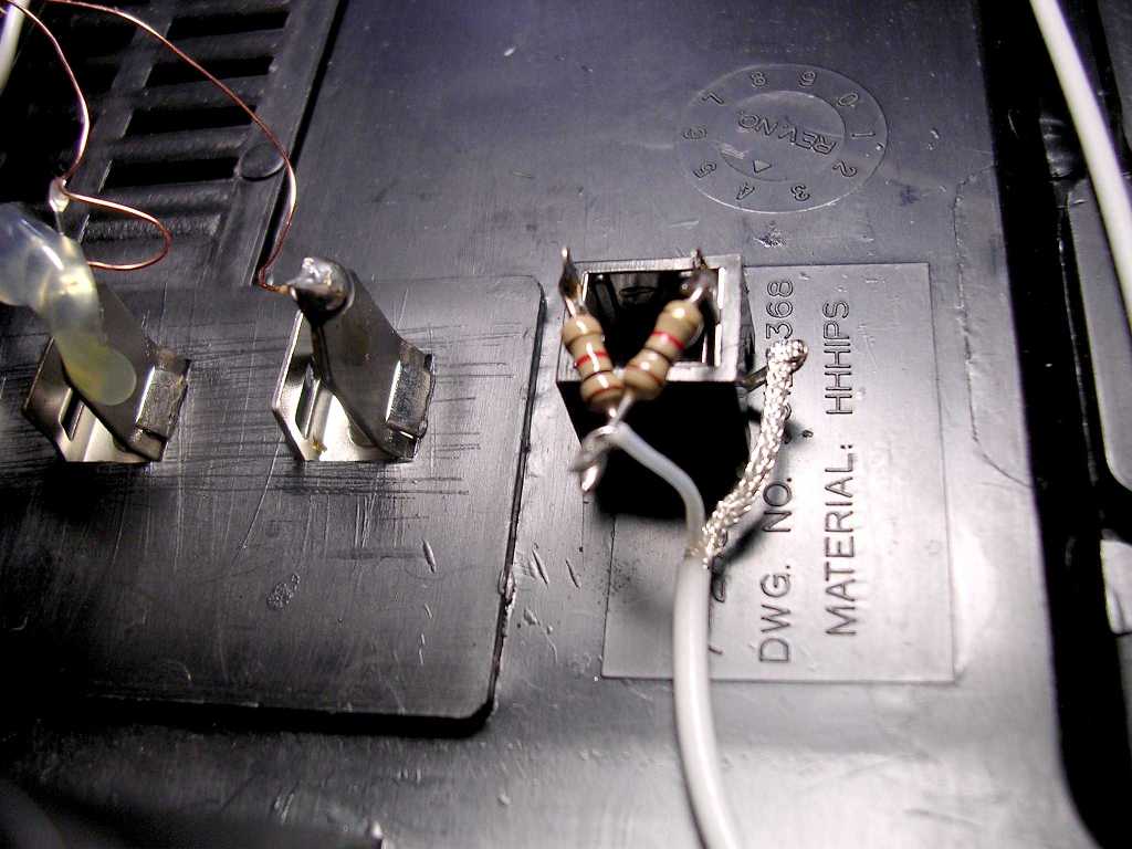
If you're sharp you will see the picture shows 1000 ohm resistors. I found 47000 ohm works better; the 1000 ohm ones allowed too much input signal.
Now you're done.
You may want to test everything before closing it back up.
Here's the secret to getting rid of the radio stations and interstation hiss when you want to listen to your alternate input:
Move the AM/FM slider switch to the middle where it doesn't make contact to either the AM or FM side. There, nothing but YOUR input.
If everything works go to boxing it back up. Put those chrome thingies on the slider switches now so you don't close it all up and see that you've forgotten them. Don't ask me how I know this! The little red line marker goes UP. Position the handle into its holder and start working the back into the front starting with the top first. The ON/OFF switch has to go into its hole and then everything else kind of goes together working towards the bottom. You may have to move those chrome thingies a little. When it finally snaps together you will want to test it again. Prior to pushing on the front knobs move the shafts fully CCW and line up the little knob markers to the '0' position. The dial knob just gets pushed on also.
Tighten the seven screws and you're done.
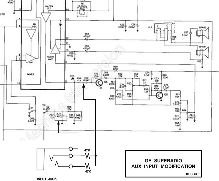
For a schematic of this mod in a .jpg format: CLICK HERE
![]()
![]()