600 ohm OPEN FEED LINE
by P. Wokoun, KH6GRT
July, 2012
(Includes 11/2014 update)
Prior to actually building the line here's some of the details I decided on:
1. Impedance to be about 600 ohms. Using #16 stranded TFFN household wire from Home Depot this results in a wire spacing of about 3-3/4 inches. I bought a whole 500 ft spool and made the antenna from the same wire. Actually, the feedline merges directly into the antenna without any connections.
2. I wanted the spacers to be round to minimize wind resistance causing fluttering and movement.
3. Waterproof spacers to prevent any interaction during wet weather.
4. Minimal deterioration effects from the sun.
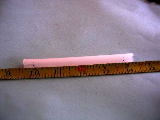
The spacer I finally decided on after much thought, browsing, looking, and experimenting was 3/8 inch polyethlyene water tubing. It was available in 25 ft coils from Home Depot.
They were easily cut into 4-1/2 inch lengths using a single edge razor blade.
They were slightly curved from being coiled up but a few moments before a hot hair dryer and they were straightened right out.
I also made a few spacers out of a harder 3/8 inch OD tubing, something called Acme PEX OT 1/4" CTS. These were used where I needed to tie supports to the feedline and needed something that wouldn't bend.
NOVEMBER, 2014 UPDATE: I can now tell you how this open line came thru 2 years of our Hawaiian sun and weather. The polyethlyene tubing turned out to be highly deteriorated by the sun. It was very brittle and easily broken. I do not recommend it for outside use. Now the PEX tubing is something else. I don't detect any deterioration in them. They are still hard, firm, and strong. I'd recommend them for all the spacers. The TFFN wire has a clear layer over the black insulation. This clear layer has generally disclored and separated from the black insulation. I see no problem from the black insulation. Maybe there's a type of wire that doesn't have this clear covering, that's what I would use. But I don't think this deteriorated clear layer is affecting operation of the wire at all.
After the spacers were cut and straightened, the ends were prepared:
At a 3-3/4 inch spacing centered on the spacer, holes were drilled using a drill just slightly SMALLER than the OD of the wire. For my #16 wire this hole was made using a #42 drill. The holes on both ends are in line axially with each other. This leaves 3/8 inch between the holes and the end of the spacer .
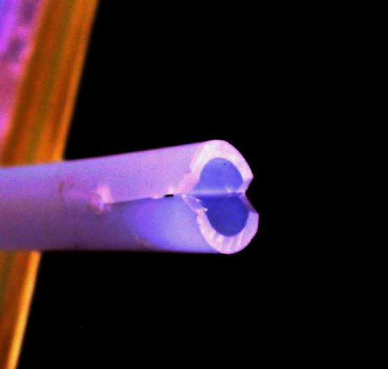
Using a single edge razor blade a cut was made from each hole straight to the edge of the tube. (USE CAUTION HERE: ALWAYS CUT AWAY FROM YOURSELF. PUTTING THE EDGE OF THE SPACER ON A SURFACE A DOWNWARD CUT WORKS GOOD.) Using the razor little 'V' notches were then made where the cut meets the end of the spacer, as shown in the picture.
Here's where these spacers made assembly so easy: If the feed wire is placed in the groove made by the 'V' notches, the spacer is soft enough to easily push the wire down into the holes.
After the wire is pushed into the holes on the spacer this is what they look like.
At this point the spacer can easily slide along the wire and positioned exactly where you want it.
Since we made the holes slightly smaller than the wire OD, that is what's keeping the ends of the spacer slightly open. Now if we squeeze the ends of the spacer together the hole will grip the wire tightly and the spacer will not slide or move.

We now finish off the spacer by using a UV stabilized wire tie wrap to close the spacer end. These spacers don't move unless you really force them and start messing up the wire insulation.
For the harder, more rigid spacers you have to pry open the spacer end to get the wire in but it works the same way.
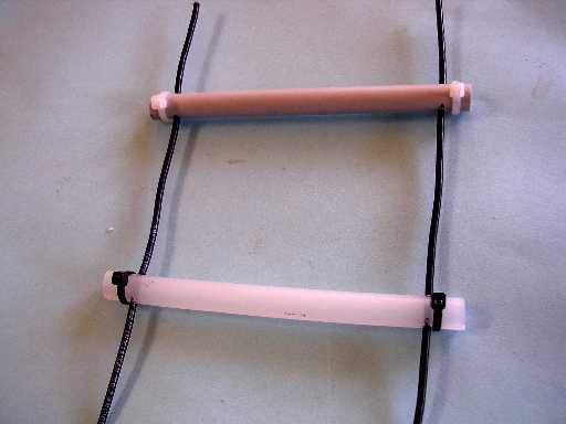
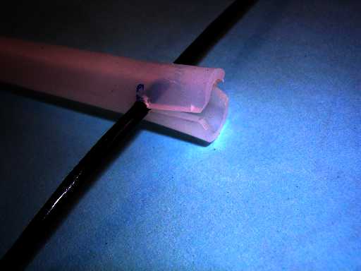
Here's what the open line looks like close up. The upper spacer is one of the harder ones I mentioned earlier. It would have the black wire tie wrap too, of course.
To assemble the open line I tightly stretched the wire between fence posts in the yard here. It was held in place by wire tie wraps with approximately the required 3-3/4 inch spacing. Then I went and snapped the spacers onto the wires. I used about a 8 inch spacing along the wire between spacers. This was followed by attaching the wire tie wraps on the spacer ends. If you have one of those tie wrap tools that tensions and cuts the ties in a single operation it makes putting on the tie wraps really easy. It took me only about 90 minutes to assemble about 90 feet of open line. Unfortunately, I didn't take any pictures during this part of assembly.
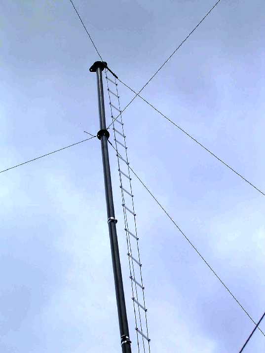
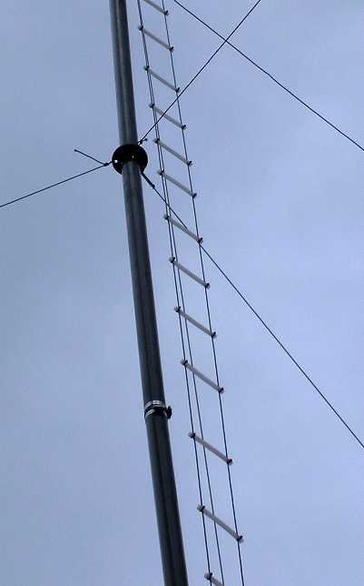
Here's the open line heading up to the antenna.
And of course, no metal near the open feedline within 2-3
wire spacings, which is 7-1/2 to 10-1/4 inches for this 600 ohm line.

