1:9 ANTENNA BALUN
by Pete Wokoun, KH6GRT
July, 2012
I recently added a 88-ft non-resonant dipole
fed by 600 ohm open line. I tried feeding it with a 1:4 balun using an autotune
antenna tuner. There were several frequencies where I was not too happy with
the SWR achieved by the tuner. Using a manual antenna tuner I was able to
achieve at least a 1:1.2 SWR; the best the autotune tuner was able to achieve
at these frequencies was about 1:1.7 or 1.8. I had this 'feeling' the 1:4
balun was not presenting the greatest match to the open feed line. After I
built and tried this 1:9 balun the autotune antenna tuner was able to bring
the SWR down to at least 1:1.2 at all frequencies. And I was able to tune
up on 75 meters also which I could not do with the 1:4 balun.
So here's how I threw mine together and the
results of its testing.
This book by Jerry Sevick is where I got
most of my information. He presents information on building baluns that really
work! I have found there is a lot of misinformation out on the internet on
baluns and ununs that results in products that just don't work well.
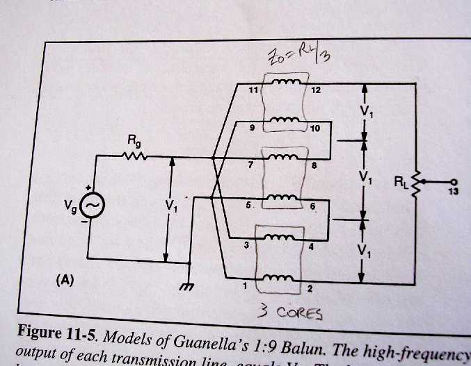
This is the circuit for the 1:9 balun. It takes three 1:1
baluns, feeds each one in parallel, and puts their outputs in series. This results
in a 1:3 voltage increase which results in a 1:9 impedance ratio. Thus a 50
ohm output impedance is increased up to a 450 ohm impedance.
One characteristic of Jerry Sevick's design is he uses transmission
lines to achieve transformation rather than a transformer-like turns ratio.
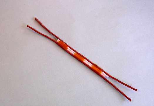
The transmission line I decided to use was two #18 teflon
insulated wires separated by two teflon insulations from #18 wires with the
center conductors removed. The line impedance as measured by the MFJ-259B procedure
was about 220 ohms. Each core required about 39 inches of this line.
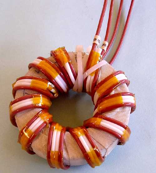
Here's one of the cores wound with the transmission line.
I used 11 turns which just about fills the ID. I used FT-240-61 cores and covered
them with fiberglass tape because the edges were sharp.
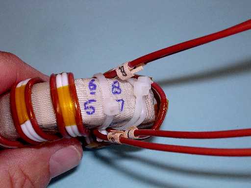
Another view of the core with the numbered leads.
All three cores are identical except for the lead numbering.
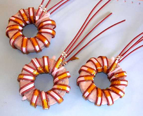
Here's the three cores assembled.
Jerry says to put 1/2-inch spacing between the cores. I
ended up with about 5/8-inch. I used a plastic cutting board for the thicker
spacers and plastic sheet for the thinner pieces. A circular hole saw easily
cut out the pieces which were cleaned up on a bench grinder.
The center bolt is a 5/16-inch x 6-inch long nylon threaded
stem with nylon hex nuts.
The input lines from all cores were kept the same length.
The estimated power rating for this balun is 500-600 watts.
UPDATE: I recently (9/2012) was able to test this balun
under high-powered conditions since I just obtained a high-powered antenna tuner
to use with my amplifier. 1500 watts CW and SSB into this balun didn't show
any problems like arcing or heating. So my current estimated power rating for
this balun is to the full legal limit.
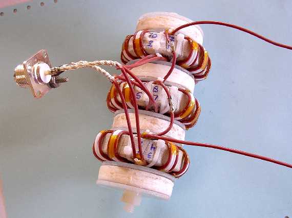
Here's another view showing the output windings in series.
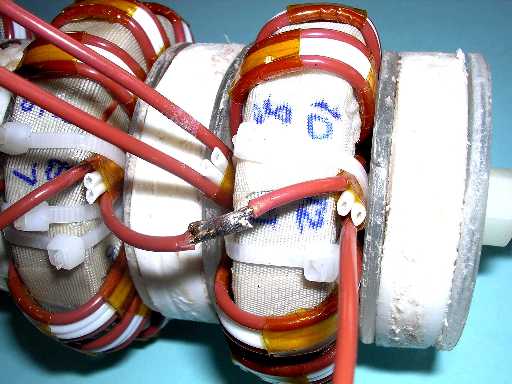
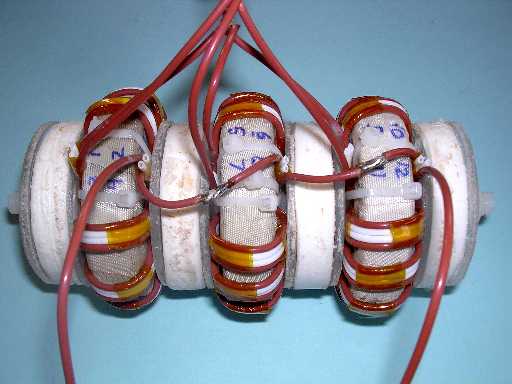
Close up view showing the spacers.

So how did testing on the 1:9 balun go?
I put a fixed 470 ohm composition resistor on the balun
output and connected the input directly to a MFJ-259B antenna analyzer.
For a maximum of a 1:1.2 SWR the frequency response is from
3.5 MHz to 30 MHz, covering all the HF bands except 160 meters. For 160 meter
coverage I would have had to use more turns on the core.
I plan to mount this balun into a plastic electrical junction
box, maybe 6 x 6 x 4 inch.
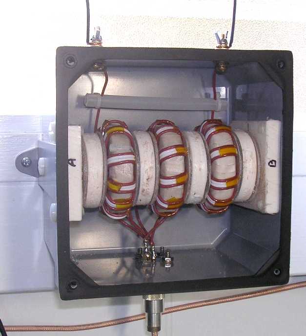
Here's the balun installed in a 6 x 6 x 4 inch non-metallic
electrical junction box. The balun is non-rigidly mounted. The A&B end pieces
are the same material as the other wide spacers. They have holes drilled just
slightly larger than the nylon nuts on the threaded stem. These end pieces are
mounted to the box by nylon screws from the outside. The balanced line hardware
is all brass.


 END.
END.