KG6MVB's Rig to Computer interface for Icom 718
WARNING!
This page describes a modification that you plug in to your radio and computer. Do this at your own risk! It's your choice to do this. I'm not forcing it on you. If you don't, hey, no hard feelings, but if you do and mess something up, don't blame me. This was designed and tested on an Icom 718 HF rig and a Dell laptop. This should work on any Icom rig that has a 13 pin accessory port, however I have only tested it on my 718. Kenwood rigs have a similar port, however the pin outs are different so beware!
Parts List:
(2) 1:1 Audio Transformers. Do NOT use step down.
(2) 4N26 Opto Isolators.
(2) IC Sockets 6 pin would be ideal. I used 8 pin.
(2) 1N914 Diode.
(2) 51 Ohm (Green-Brown-Black) resistor.
(1) RS-232 Cable (mine was an old Null Modem Cable).
(1) Dual Shielded patch cable. I cut off the RCA ends.
(2) 1/8 Stereo Plugs. I used one plastic one and one metal one to tell them apart.
(1) 13 pin din plug. Mine is for a Kenwood. I'm using it on an Icom. They are universal.
(1) Six conductor (or more) cable. Shielded preferred.
(3) Snap on ferrite cores.
(1) Project box.
(1) Perf board.
I am the type of person who likes to push every button, twist every knob, and try every option on any piece of electronics I get my hands on. After purchasing my Icom IC-718, I discovered the page in the manual where that mysterious 13 pin accessory connector on the rear was documented. Since I know that I can not be cured, I had to put it to use. As a bonus, If I can build it myself - need I say more?
The main purpose of this device is to provide total isolation between the computer and the rig. You don't want to create ground loops connecting it all directly. Computer hash in your HF rig will make you miserable, and RF in the computer...isn't Windows unstable enough?
Many of the parts I used were from my junk box. For the parts I did not have, I found them at All Electronics, which is a electronics surplus store about 10 miles from work. I do NOT recommend Radio Shack for parts, as they are very overpriced, if they even have the part! If you do not have an electronics store in your neck of the woods, I would suggest looking online. The only part I had trouble finding was the 13 pin DIN connector. I found one at HRO - it is for a Kenwood, but they are universal.
The audio is coupled through 1:1 transformers. These are the type you find in modems. You do not want to use step-up or step-down, as they will change the levels. I was happy to discover during testing that both the modulator input and the output on the 13 pin connector are at line level. Computer sound cards are also at line level, so this part is super simple. I was able to use the sound control panel within Windows for all my audio adjustment. Since I didn't want any possibility of ground loops, I did not connect the grounds together. In the pictures you will notice that I have one plastic plug, and one metal one. This is only so I can tell which one is which. The cable I used was an old shielded patch cable, which I cut the RCA ends off. Every piece of software I looked at uses the left channel (tip), so connect there. This completes the audio portion of the circuit.
Next, you need to control transmit / receive. Most software will toggle either the RTS or the DTR line. I chose RTS (pin 7). What this means, is when the software wants to transmit, that pin goes high (positive voltage). In receive, it returns to zero. On my ham rig, the ptt circuit floats high, and when you pull it down, you transmit. This circuit could have been done several ways. one way is with a transistor as a switch. Unfortunately, this does NOT provide total electrical isolation. The second way would be a relay. The third, is an opto isolator. Inside the opto isolator, there is an LED and a phototransistor. When you light up the LED, the transistor conducts. Since the only connection is light, you maintain your isolation. This LED only requires 1.18 volts (1.5 max) with a current draw of 100mA. Breakdown voltage is only 6 volts, so we better put a dropping resistor in there! I put the reverse bias diode, so if we have reverse voltage, it has somewhere to go, and doesn't build up to the breakdown voltage. On my initial design, I assumed we were dealing with 12 volts. I put in a 1.2k resistor, and nothing happened. Troubleshooting showed me that my laptop was only putting out 5 volts. I turns out this is typical. Most desktop systems use a 12 volt standard, and laptops 5 volts. I changed the resistor to 51 ohms, and it works well now.
My rig (Icom IC-718) has the ability to do FSK RTTY. I found a RTTY program that toggles this on the TXD line (pin 3) of the RS-232 port. This was easy. I just copied the PTT circuit! This is the lower of the two opto isolator circuits. If you have no use for FSK RTTY, just omit this portion. You will still be able to do AFSK RTTY without this portion of the circuit.
When shopping for parts, I found a small enclosure and a matching perfboard designed to fit inside. The perfboard is the type with pads for all holes, and no solder mask. This allows you easy solder bridges, which I am using to make the circuit (see photos below). Since making solder bridges can keep your iron on one spot over and over, I decided it was worth spending a few cents more, and used sockets for the opto isolators. I didn't want to cook them. The RS-232 connector is the female side. When looking at the connector, pins are numbered from right to left, top to bottom (as shown on the schematic). The DIN is a male connector, and pins are numbered left to right, top to bottom when looking at it (also as shown on schematic). You want to keep the cables as short as practical. You don't want to turn them into antennas. In my initial design, I had a problem where the transmit relay in the rig would chatter on full power RTTY. What was happening, was as soon as the rig was keyed, RF would get in, and unkey the rig. My RF environment is not favorable, so I may be an extreme example (you can read about this on my main page). Shortening the rig to interface cable down, and installing ferrite cores solved this problem.
You will need software! One of the great things about Ham radio, is there is so much out there for free, and most of it doesn't need much computing power. My laptop is a joke by today's standards. It is a Pentium 133 Mhz with 48Mb ram. The OS is Windows 98. The only extra is a wireless lan PCMCIA card. For PSK I am running Digipan 2.0. Wow, what a great program. You can watch multiple psk conversations, and just click the one you want to put on the big window (the one calling CQ). Digipan can be downloaded from http://www.pavane.net/digipan/digipan.htm. For SSTV, I am using MMSSTV and for RTTY I am using MMTTY, both from JE3HHT - Makoto Mori. More great software! You can download both of these from http://mmhamsoft.amateur-radio.ca. For computer generated and decoded CW, I am using Hamscope. You can download Hamscope from http://www.qsl.net/hamscope. I'm sure this interface will work with other programs as well.
Operation is easy. I do recommend a few things. Dedicate your sound card to rig operation! Turn off all the Windows sounds. You don't want to send out all the cute little Windows noises over the air (and it will). On the 718, you can leave the microphone connected, just turn the mic gain all the way down (in the menu). If you leave it up, it will transmit room audio, and with PSK, you are operating in the non phone parts of the band! The mic gain settings do not affect the accessory connector. You should also turn off DSP. For PSK, I adjust the incoming audio level (with the windows mixer) so you see the blue waterfall with just barely a small speckling of yellow. The rig's volume control has no effect on this either. For the output level, make sure compression is off, and adjust so you are NOT invoking the ALC. For the record, PSK is a low power mode. I found that once I set the levels, they are good for all three programs. You will of course need to do some experimentation with this.
Another extra benefit to this interface. Have you ever wanted to record a QSO? You can use Windows sound recorder to do this!
I hope to work you on PSK soon. Look for me at 14.070.
73 de KG6MVB
Tom
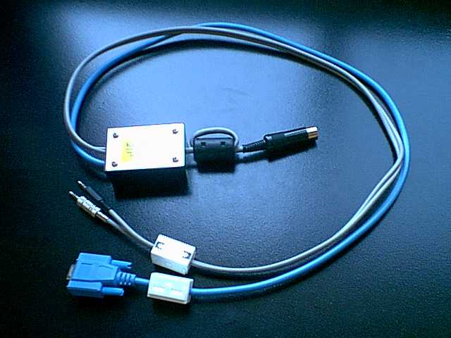
Finished interface in case.

Component side of interface.
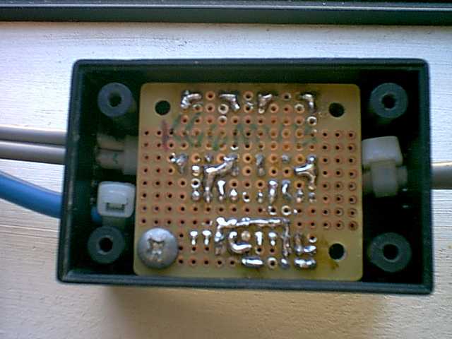
Solder side of interface.
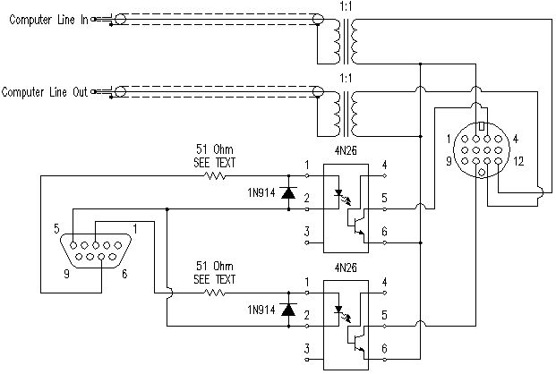
NOTE: Labels for pins 4 and 6 on both 4N26 opto isolators are transposed. I will fix the schematic at some future date. Thank you John ZL2BH for catching this.
Schematic Diagram. Click here to download pdf version.
Back to my main page
This page was updated on June 2, 2021