KG6MVB's modified E-DC-5B Power Adapter for VX-150
WARNING!
This page describes a modification to the power adaptor. Do this modification at your own risk! It's your choice to do this. I'm not forcing it on you. If you don't, hey, no hard feelings, but if you do perform the modification and mess something up, don't blame me. This modification is not endorsed by Yeasu, Vertex Standard or anyone else. The opinions expressed on this webpage are mine, and only mine, and are opinions, not hard proven fact. Any measurments are based on my own VX-150 radio and E-DC-5B power adapter, and may vary from one unit to another.
Back in October 2002, I set out to purchase my first HT, and try out VHF. When I got my license, I figured I would just be on the HF bands. I wasn't all that interested in "local" line of sight radio. Also, being on a very low budget, I didn't want to spend very much. I was going to buy the Icom T2H, but saw the Vertex VX150 down at HRO. At that time, it was selling for $120. Well, adding rechargeable batteries to the t2h, and finding out that you can't charge it and use it at the same time convinced me to buy the VX150. I also purchased the E-DC-5B power cord. $30 for a power cord! The radio only cost $120 (which later dropped to $89). If I were to buy that 1000 dollar rig, would the dc power cord cost me $250??? Ok, that's enough ranting. At least it is filtered.
Doing some after the sale research, I found out that these radios like to blow their finals! Although there is no official confirmation from Yeasu, based on my research in Yahoo groups, Eham etc, it seems that the ones with blown finals were using the radio with external power and/or antennas. A personal observation - When I used the radio on battery and rubber duck, It never got more that slightly warm, even at 5 watts. I also never noticed any problems using the radio with an external antenna. I have used a 5/8 wave on the roof of the car, and a homemade yagi. Again, no unusual heating (note, both these antennas are under 1.5:1 swr). However when I plugged it into the car for power, the case became uncomfortably hot. This happens even with the stock rubber duck antenna.
One would think that with a higher voltage, the final wouldn't have to work as hard. Looking at a schematic of the radio, the full input voltage is sent to the final amp. However the output power doesn't change above 7.2v. They must be doing something before the final to control output power. The radio knows the voltage (Function 37). The final probably is doing more work at the higher voltage, as the radio is cutting input power to compensate (just a theory). Well, regardless, the bottom line is the radio gets very hot when transmitting with 13.8v input. Heat kills.
I quickly decided that using the $30 power cord was a bad idea, except for charging the batteries. I don't want to cook my radio! Again, I'm a cheap ham, and didn't want to buy a separate mobile rig. At 5w, the batteries don't last all that long. 30 bucks for a charger! I'm not a happy camper here.
If the radio can run happily on the internal batteries, why not cut down the voltage from the car? I didn't want to modify the radio itself (I want to keep the warranty in case the finals do blow). Making a special regulated outlet in the car was an idea, except that I don't always drive the same car. I opened up the adapter, and noticed there is a little bit of room inside (not much, but some). Off to the junk box I go...
The only part I purchased was an LM317T regulator. The rest came from my junk box. It set be back $1.99 at Radio Shack. Many of you will pick on Radio Shack, but sometimes they are convenient if you just need one or two items. Paying two bucks for a twenty cent part seems outrageous, but compared to driving 30 miles one way to the nearest real electronics store, they are worth having around.
Here is the parts list: (one each)
LM317T regulator (Radio Shack 276-1778)
Heat sink. You will need one you can cut to fit in the top of the case. I scrounged mine from a dead PC power supply.
240 ohm resistor (I used a 220 ohm)
5k ohm pot
1uF Tantalum or 25uF aluminum electrolytic capacitor (I used a 47uF)
perf board
As you can see, the values are not all that critical. Hey, this is the power supply, not RF microwave circuits. I substituted values with items I had on hand.
Remove the four screws that hold the cover on the filter. The whole board will lift out. Be careful not to break the negative wire. The pictures below explain the construction. Sorry about the poor quality, but this is amateur radio, not photography! I cut the perf board to fit behind the screw hole supports. The heat sink was cut to fit up at the top. Make sure you have enough clearance between the existing heat sink and your new one. Both are at their own respective output potential, so if they touch, you just eliminated the whole point of this mod (but you won't blow anything up). Remove the white wire at the output, and connect to the output of your regulator. The red wire you see in the pictures is from the output of the filter to the input of my regulator. The Black wire is a ground wire that I routed through a slit in the board, and soldered along with the ground wire that I told you not to break (above). Also, if you use an electrolytic, watch the polarity!
Adjustment:
Put the main board back (don't forget the fuse and spring), connect to 12v supply, and adjust the output voltage with the pot. I just held mine together while I adjusted it (if you close it up, you can't get to the pot). The pot in mine is real sensitive. I set mine to 8.9V. If you don't have a voltmeter, plug it in to the radio, choose function 37 and it will tell you the voltage. Once adjusted, put the cover back on. Congratulations! You should notice that the voltage stays at 8.9, regardless of the input voltage. Start your engines! Hey, now you are feeding 13.8 to the input, but you are still putting out 8.9. Aaah, the beauty of regulation. I added a label to mine, proudly stating the new output voltage, date and my call sign.
Why 8.9 and not 7.2? Looking at the schematic of the radio, there is a simple diode switch between the battery and external voltage. The higher voltage will be the one used. The NiCads float up to 8.2 when full, so we want a bit more than that. Also, I still want to charge my batteries from the car. To fully charge a NiCad, you need minimum of 1.41 volts per cell. The battery contains six cells, so we need 8.46 at the battery. I simulated the battery in place, and measured the voltage being sent to the battery. I adjusted for 8.5 volts at the battery connection. The input voltage was at 8.9 when I reached this value. Yes, I know that to charge a NiCad, you want to control the current, not the voltage, but you do need to have enough voltage present! The charging control is (still) inside the radio. I have tested, and yes, it does charge.
Final notes:
I've been running the radio daily on the new DC cord for over a year. The filter/regulator gets a little warm, but not too bad (I'd rather the heat be there than in the radio). The radio stays cool. I've asked about the signal quality and nobody has reported the usual car issues (whine).
Yeasu used 16v caps in the filter. Do NOT use with more than 16 volts!
There is a resistor on Yeasu's filter board labeled 4.7k. That's a 1k in there. Hmmm....
Some have asked me if you can use the VX150 with the AC power adaptor. Bad Idea! The NC-72B adapter is only rated for 500mA. At full power, the radio draws 1.3A. You will notice that it is labeled as "Battery Charger". It is ok to listen while charging however, just don't transmit. If you are concerned about overcharging the battery, the charge current is low enough that a little bit wont hurt (much). If you cover the third contact in the battery compartment (lower left corner), it will not charge, and can be left on the power adaptor indefinitely. I keep a small piece of paper behind the battery. If I don't want the battery to charge, I move it over the contact. If I want it to charge, I move it out of the way.
The charging circuit is independent of the rest of the radio. It will charge the same, off or on. It takes about ten hours to fully charge the FNB-64 battery pack (from fully discharged). If you are using higher capacity batteries, it will take longer, as the charge current is around 70mA. Divide the battery capacity by the charge current to find the time.
How do you know if the battery is full? The radio has a built in voltmeter (Function 37). I set the P1 key, so I just hit F-7 to see the voltage. When my batteries are fully charged (with the charger removed), I see a reading of 8.2-8.5 volts. Nicads do NOT discharge in a linear manner. If you watch the voltage over time, you will see that it quickly drops to 7.2 volts, and will stay there (and 7.1) a long time. Once you drop to 7.0, the end is near. It will quickly discharge the rest of the way. Mine cuts off at around 6.0 volts.
BTW - I've changed my mind about two meters. I've been on T hunts, worked the ISS, and it can be a challenge to see just how far away you can get with line of sight. I've had fun, and after all, that's what this hobby is all about.
73 de KG6MVB
Tom
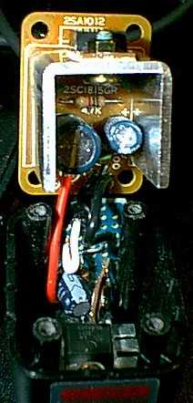
Original Board with mod below.
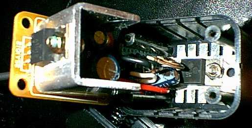
Modified top section.
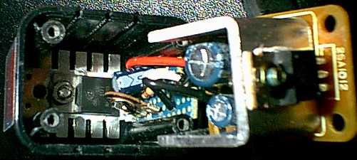
Modified side view.
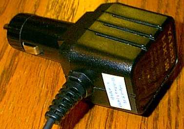
Complete.
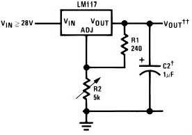
Schematic.
Back to my main page
This page was updated on January 20, 2004