BEE
Vacuum Tubes
" If it don't glow in the dark, it ain't Radio."
Transistor amplifiers have come a long way in the last 20 years. Today 600 watt transistor amplifiers are
readily available. While the power levels have increased, these amplifiers remain subject to failure from heat
and SWR. Vacuum Tubes are much more rugged, surviving these same conditions over extended periods of time.
The most common cause of failure in tube type Amplifiers is improper tuning.
TUBE DIODES
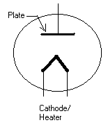
Below are the schematic symbols for Vacuum Tube Diodes.
Directly Heated Cathode Indirectly Heated Cathode
The basic elements of a vacuum tube are illustrated in the drawings above. They employ a heating element
very similar to the incandescent light bulb. The element in a light bulb is designed and composed of material
which will produce "white" light, while that of a tube is designed and composed of material to produce heat.
They are enclosed in a glass envelope (sometimes metal or ceramic) from which the oxygen has been
removed and in some cases partially replaced with inert gas. A chemical called a "getter" is often painted on
the inside of the glass surface, (ever wonder what that silver looking stuff was?) it combines with and
removes any remaining oxygen molecules which would interfere with current flow in the tube and shorten
the life of the heating element.
The next element is the cathode which is the element that receives the negative voltage potential.
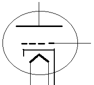
As you can see above the heater and the cathode may be the same element or they may be separate as
in the drawing on the right. Heating the cathode results in electron emissions. A cloud of
electrons will be emitted from a hot cathode.
The first number of a tube designation is usually it's filament voltage. (6LF6,12AU6,5R4,30LF6)
As with all things electronic there are exceptions to the rule so check the manual.(811A,572B)
The final element in our diode is the plate, represented by the horizontal element at the top of the drawing.
The plate is normally in the form of a cylinder surrounding the heater and or cathode. It is the element that
receives the positive voltage potential which maybe anywhere from 67 volts to several thousand volts.
Summing up, the negatively charged electrons emitted by the heated cathode are drawn toward the positively
charged plate when an external voltage is applied. Due to the electrostatic field created by this external voltage,
more current will flow then can be accounted for by the cooking off of electrons due to heating the cathode.
As the plate voltage increases so does the plate current.
If an AC voltage is applied, current will only flow in the
tube when the cathode is negative in relation to the plate. This results in a pulsating DC voltage that can be
smoothed by a filter circuit into a nearly pure DC source.
Tube type rectifiers have been, for the most part, replaced by semiconductor diodes.
Triodes
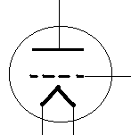
Above we looked at a vacuum tube with 2 active elements, a cathode and a plate.(we don't count the heater)
Now we will add an additional element between the plate and cathode, making 3 active elements, we have a
Triode.
The third element is the control grid. You may think of it as a screen door between the cathode and plate.
Below are the schematic symbols for directly and indirectly heated triodes.
The control grid is located very close to the cathode. Due to it's location and construction it has much more
control over the plate/cathode current flow then does changing the voltage applied to the plate(Plate Voltage).
A change of 1 volt on the control grid may make the same change in plate current as a 100 volt change in plate
voltage.
If a resistor is placed in series with the Plate,
the applied voltage will be divided between it and the plate.
The changes in plate current produced by
changes in grid voltage will result in voltage changes across the Plate Load resistor.
This is the output signal.
E=IR
In the case of multielement tubes, the recommended plate voltage will produce enough current flow to heat
the plate to the melting point. Adding a negative voltage to the control grid will reduce the current flow to a
safe level. Making small voltage changes on the control grid will result in much larger changes in the plate circuit
(or amplification).
Basic Amplifier Circuit Coming Soon.


