Antenna Theory (sort of)
When it comes to antennas, SIZE DOES MATTER.
This is really an analogy rather than theory. The purpose is to hopefully provide you with information
that will allow you an understanding of how an antenna operates and allow you to evaluate their
configuration.
Resonant antennas have been described in many different ways. The definition that come to mind most often is:
An Antenna which presents a non-reactive (resistive) load at the design frequency.
This is a very broad definition, it includes1/2 wavelength dipoles with 72 ohm feed point impedance at 1/2
wave above ground, quad loops with 120 ohms, 1/4 wave verticals with horizontal radials at 35 ohms,1/4
wave verticals with radials dropped at 45 degrees from horizontal at 50 ohms, 1 wavelength dipoles with up
to10,000 ohms depending on what size wire they are made of. These are all resonant antennas by the above
definition. The operation of all these antennas(even the quad loop) as well as the majority of antennas can be
described and understood applying the same principles as I will describe for a 1/2 wave dipole.
(not all ,but most)
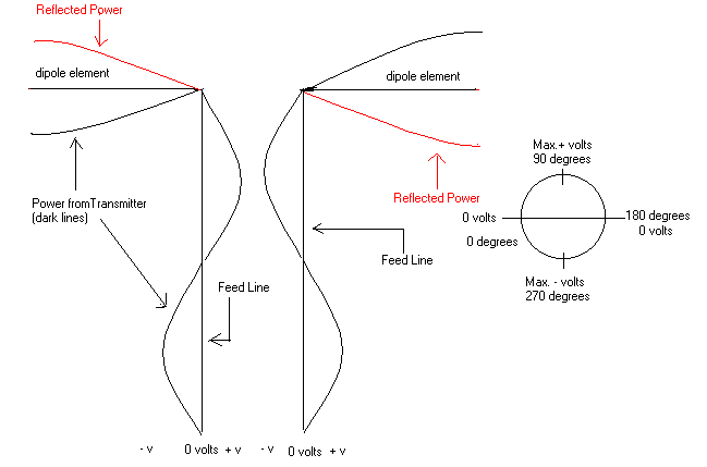
First, a description of the drawing above. The horizontal elements labeled "dipole element" represent the two
1/4 wavelength elements that make up a 1/2 wavelength dipole. The vertical elements represent the feed line
with a sine wave representing the RF power(in black) added to them, at the bottom you will see the 0, max.+
and max.- voltage labels.( notice that the power applied to the lines are 180 degrees out of phase.) The red
lines represent reflected power which I will explain. There is also a circle labeled "0 volts - 0 degrees"," Max.+
voltage - 90 degrees", "180 degrees which is again 0 volts", "270 degrees Max.negative voltage" and returning
back to 360 or 0 degrees - 0 volts again. This represents one complete cycle of RF electrical energy. I hope
you can see the correlation between the circle and the sine waves on the feed line. Moving clockwise around
the circle is the same progression as the energy representation on the right leg of the feed line,
counter clockwise matches the left leg. With that out of the way, on to the dipole.
1/2 Wavelength Dipole Antenna
Starting at the feed point,( where the vertical feed line meets the horizontal elements.) the RF energy from the
feed line moves out along the 1/4 wavelength dipole elements. Most of the energy is converted to electromagnetic
waves and radiated into space. When the energy which was not radiated reaches the end of the element, it is
reflected back toward the feed point(red lines in drawing), much as a mirror reflects light. Since this energy
has traveled 90 degrees out and 90 degrees back, it arrives back at the feed point 180 degrees out of phase
with the incoming energy from the feed line. Since a large portion of this energy has been radiated the small
amount leftover is canceled out by the much larger incoming energy from the feed line. The remaining incoming
energy then proceeds long the element repeating the cycle. Referring to the circle above, it is easy to see that
at any point the energy at 180 degrees (straight across the circle) is of opposite polarity.
Next we get to play "but what if". What if the element is too long or too short? Then the reflected energy will
arrive back at the feed point either leading or lagging (capacitive or inductive) in phase the incoming energy
from the feed line producing a reactive (non-resonant) feed point and incomplete cancellation.
While this is not antenna theory it may help you as it has me to understand what is happening
in an antenna system.
*** The tip or end of a antenna is always a high voltage point and the starting ***
point for evaluating an antenna.
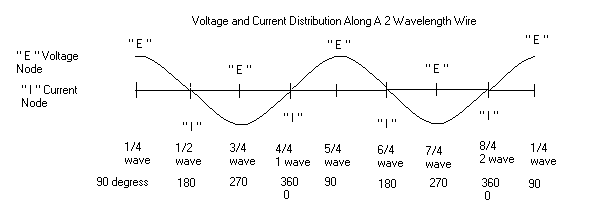
From the graph above you can see that there is a voltage or current node every 1/4 wavelength.
The current("I") nodes are low voltage, lower impedance points while the voltage ("E") nodes
are high voltage, high impedance points.
( the simples way to feed at a voltage node is to add 1/4 wavelength of wire between the feed point
and the feed line) after all, 1/4 wave from a voltage node is a current node The wire could be feed
with a balun and coax at any of the current ("I") nodes. It should be noted that the wire would be
different lengths for different frequencies while maintaining the same "E" and "I" distribution.
What if the antenna elements were 1/2 wavelength each, making it a full wavelength long?
What would be the effect at the feed point if center feed? (+/+ -/-)
What if it were 1 and 1/2 wavelength long?
More to come
What if you had two dipoles. You feed one normally and mounted the other 1/4 wave above it. If you bent the
legs up on the bottom one (that you are feeding normally) half way along them or 1/8 wave from the feed point
and bent the legs down from the top one at the same point and connected them together .Would you then have a
Quad loop made-up of two dipoles, the upper dipole being voltage feed from the ends of the lower dipole?


