Some Generally useless Ramblings on Tuned Circuits
and
how they apply to multi band or (Trap) Dipoles!
by KG4BIN David Morgan
The trap antenna, was invented mostly for convenience.
It was not invented for maximum efficiency. As with all antennas, trap
antenna adherents claim they get good results--and they do. But whether
they get better results than they would with other types of antennas of
comparable size, is a question very hard to answer. The answer would require
that the trap antenna and the alternative be placed in nearly the same
position at the same height, and few of us can afford the space, time,
or money for such comparisons. However the trap antenna is cheap, easy
to build and can cover many bands, without having to resort to a tuner.
The most common type of trap antenna, is the parallel
tuned circuit, that is resonant at or just below the edge of the higher
frequency band to be covered, with extensions to make up the length of
the lower band. These antennas will be shorter than a full-size dipole
at the lower frequency, since the trap acts like an inductor at the lower
frequency, much like a mid-element loading coil. However, the inductive
reactance is not a product of the coil alone, but of the tuned circuit
making up the trap.
Virtually all radio communication involves the
use of resonate circuits, in one way or the other. Any tuning element,
involves resonance; without it we could neither transmit a stable signal,
nor could we select the desired signal with our receivers. In the old days,
when big spark gaps furnished the transmitted RF and mechanically shaken
cohers were the receivers, resonate circuits as such, were unknown-and
radio's usefulness was sorely limited.
If you're designing a circuit and your major requirement,
is to obtain resonance at some single desired frequency, you have an infinite
number of values to choose from! No matter what size capacitor you choose
to use, it will have a definite capacitive reactance at your desired frequency,
and all you will have to do to achieve resonance is to provide an inductive
reactance of exactly the same value at the same frequency.
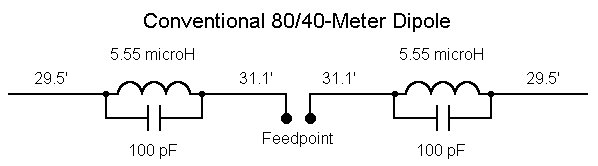
Let's look at the more conventional trap antenna
and simplify it to just 2 bands, like 80/40 or 20/10. A full size #14 copper
wire resonant dipole will have a gain of about 2.1 DBI in free space, but
it has this gain only in one ham band. We can use the gain figure, as a
standard against which to measure trap antennas for two bands. The first
thing we see is that performance of a two band trap antenna of conventional
design, depends very heavily on the Q of the trap. There are many trap
designs, but here is a table of one pretty good design with coils of various
Qs. The gain is for free space.
       Q           High-Band Gain (dBi)      Low-Band Gain (dBi)
       50                 0.7                       1.7
      100                 1.4                       1.8
      200                 1.8                       1.9
      400                 2.1                       2.0
      800                 2.2                       2.0
The Q of a coil, is the ratio of energy
stored in the coils magnetic field, to the energy
dissipated in the coils resistance and radiation
losses!
Long thin coils, require more wire and so have a
higher resistance, while at the same time producing smaller magnetic fields.
Large short coils, also have smaller magnetic
fields and because of it's size, is more subject to radiation losses.
The "square coil", strikes a balance between
large magnetic fields, for energy storage and small enough size, to minimize
radiation, and so has an optimum Q.

The voltage drop across any single impedance in a
resonate circuit, is affected by the Q as shown here. This circuit has
a Q of 100, since 1 amp of current overcomes losses to maintain 100 amps
of circulating energy. If the impedance of the capacitor is 1 ohm, a voltmeter
will measure 101 volts across the capacitor. Although only 1 amp is flowing
in the external portions of the circuit. The meter impedance must be taken
into account, since it will load the circuit and effectively reduce Q.
Avoid low-Q trap coil designs. It is fairly easy
to homebrew airwound coils with a Q of 200, and common coil stock usually
meets this figure. Even the best series-wound coaxial trap coils will not
have Qs higher than about 400, and most coils with Qs claimed to be higher
than 400 will not retain that Q under the influence of a chemistry-lab
atmosphere. Nonetheless, a dipole with a gain of 1.8 or so will not yield
results noticeably worse than a full size dipole, since a half dB of lost
gain translates into less than a tenth of an S-unit.
The sample conventional 80/40-meter trap dipole
in Figure 1 uses traps tuned to 6.75 MHz. With a Q of 200, the traps equalize
performance on the two bands at just above 1.85 DBI in free space. This
is only about 0.35 dB down from a full size dipole for each band.
Coaxial-Cable Trap Construction
Coaxial-cable traps are inexpensive, easy to construct,
stable with respect to temperature variation and capable of operation at
surprisingly high power levels.
Coaxial-cable antenna traps are constructed by
winding coaxial-cable on a circular form. The center conductor of
one end is soldered to the shield of the other end, and the remaining center
conductor and shield connections are connected to the antenna elements.
The series-connected inner conductor and shield of the coiled coaxial-cable
act like a bifilar or parallel-turns winding, forming the trap inductor,
while the same inner conductor and shield, separated by the coaxial-cable
dielectric, serve as the trap capacitor. The resultant parallel-resonant
circuit exhibits a high impedance at the resonant frequency of the trap.
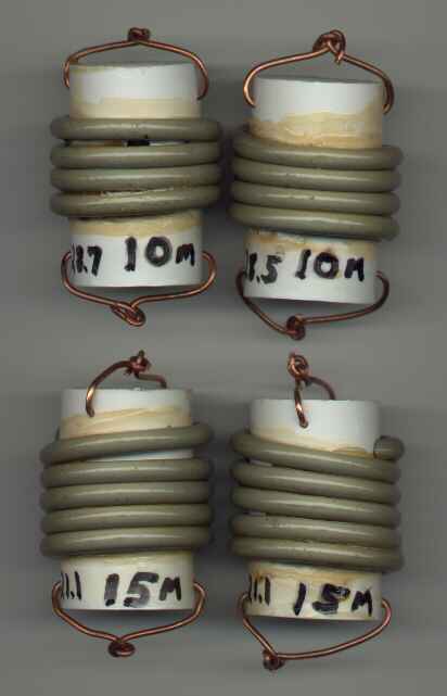
I constructed the traps using RG-58/U coax.
PVC pipe couplings were chosen for the trap forms: they are very
inexpensive and readily available in useful diameters. 12 gauge solid
wire was used to form "bridle wires" for electrical termination of the
coax and electrical and mechanical termination of the antenna wire elements.
The coax turns were spread slightly until the desired resonant frequency
was reached, as measured by a dip meter. After adjustment the coax
turns were secured by coating with lacquer.
Table 1. Specifications of the traps used
in this antenna.
|
band
|
trap form
|
coax length
|
coax turns
|
design frequency
|
actual frequency
|
|
10 meters
|
3/4" PVC coupling (1.375" OD)
|
20.25"
|
4
|
28.85 MHz
|
28.5 MHz, 28.7 MHz
|
|
15 meters
|
3/4" PVC coupling (1.375" OD)
|
26"
|
5.25
|
21.225 MHz
|
21.1 MHz
|
|
20 meters
|
1" PVC coupling (1.625" OD)
|
35.5"
|
6
|
14.175 MHz
|
14.2 MHz
|
|
30 meters
|
1.25" PVC coupling (2.0" OD)
|
46.25"
|
6.5
|
10.125 MHz
|
10.12 MHz
|
|
40 meters
|
1.5" PVC coupling (2.25" OD)
|
61"
|
7.75
|
7.15 MHz
|
7.15 MHz
|
 The
10 and 15 meter traps, wound on 3/4" PVC pipe couplings.
The
10 and 15 meter traps, wound on 3/4" PVC pipe couplings.
Trap Connections
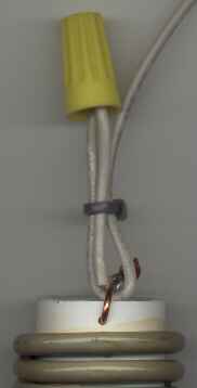 I
used this simple method to connect the traps to the antenna wire elements.
I soldered a short (approximately 2") wire pigtail to the bridle wire on
each end of the trap. Then the antenna wire was looped through the
trap bridle wire and secured to the pigtail using an electrical wire nut.
This made trimming the lengths of the antenna elements easy, as the connections
could be readily disassembled. Once the element was tuned, the connection
was soldered, to prevent oxidation. When the antenna trimming was complete
I used a nylon cable tie to secure the antenna wire loop to the pigtail
to strain relieve the connection.
I
used this simple method to connect the traps to the antenna wire elements.
I soldered a short (approximately 2") wire pigtail to the bridle wire on
each end of the trap. Then the antenna wire was looped through the
trap bridle wire and secured to the pigtail using an electrical wire nut.
This made trimming the lengths of the antenna elements easy, as the connections
could be readily disassembled. Once the element was tuned, the connection
was soldered, to prevent oxidation. When the antenna trimming was complete
I used a nylon cable tie to secure the antenna wire loop to the pigtail
to strain relieve the connection.
I used 12 gauge stranded household electrical
wire for the antenna elements. This wire is very inexpensive when
purchased in 500 foot spool quantities at home centers. The insulated
jacket causes the wire to have a velocity factor somewhat lower than that
of bare copper wire.
Center and End Insulators
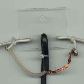 The
antenna center insulator was constructed from a piece of scrap Plexiglas.
The center of a half-wave dipole is a current feed point so just about
any insulating material will work here. Plastic cable ties are used
to secure the antenna elements and the RG-58/U feedline to the insulator.
A rope attached to the topmost hole is used to support the antenna center.
The
antenna center insulator was constructed from a piece of scrap Plexiglas.
The center of a half-wave dipole is a current feed point so just about
any insulating material will work here. Plastic cable ties are used
to secure the antenna elements and the RG-58/U feedline to the insulator.
A rope attached to the topmost hole is used to support the antenna center.
Choke Balun
I constructed a choke balun near the antenna center
insulator by wrapping approximately 6 feet of the antenna coaxial-cable
feedline as a single layer winding on a scrap polyethylene food container
that was approximately 4 inches diameter. I used cable ties through
small holes drilled in the container to secure the coax winding.
Some amateurs argue that a balun is not necessary
when feeding a dipole with coax. The simple choke balun used here
is trivial to construct, and I do not feel it is worth the risk of feedline
radiation problems to omit it.
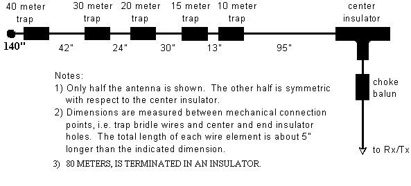
Antenna Dimensions
The final dimensions of the antenna are shown below.
If you try to duplicate this antenna you should start with longer lengths
and then trim as necessary, as the lengths will be affected somewhat by
height above ground, and by proximity to building. An antenna analyzer,
such as the MFJ-259 that I used, greatly speeds the trimming process.
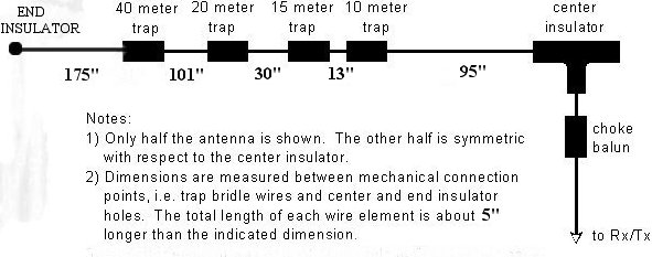
If you are not interested in the 30 meter WARC
band, here are the dimensions of the antenna without the 30 meter traps.
You may note that the 80 meter end sections are significantly longer in
the version without the 30 meter traps: much of that difference may be
due to the larger percentage of the 80 meter section length.
Electrical Measurements
One of the most often quoted disadvantages of trap
antennas is reduced bandwidth. But the useful bandwidth of the coaxial
trap dipole described here is sufficient for no-tuner use over much of
the 6 bands. As the measurements in Table 2 illustrate, the antenna
performs with better than 2:1 SWR over the entire 10 and 15 meter amateur
bands. Almost all of 20 meters is usable with less than a 3:1 SWR.
The 40 and 80 meter bands were trimmed for operation within the CW band
segment.
Table 2. 2:1 and 3:1 SWR Bandwidth
(Measured with MFJ-259 Antenna Analyzer).
|
amateur band
|
2:1 SWR
|
3:1 SWR
|
|
10 meter (28.0-29.7 MHz)
|
2.2 MHz
|
4.23 MHz
|
|
15 meter (21.0-21.45 MHz)
|
640 kHz
|
1.04 MHz
|
|
20 meter (14.0-14.35 MHz)
|
190 kHz
|
330 kHz
|
|
30 meter (10.1-10.15 MHz)
|
100 kHz
|
190 kHz
|
|
40 meter (7.0-7.3 MHz)
|
50 kHz
|
110 kHz
|
|
80 meter (3.5-4.0 MHz)
|
60 kHz
|
200 kHz
|
Table 3 contains the resonant frequencies and
SWR, 2:1 SWR limits, and 3:1 SWR limits of the antenna as measured after
the final trimming of each of the elements.
Table 3. SWR vs. Frequency (Measured
with MFJ-259 Antenna Analyzer).
|
SWR
|
10 meter band
|
15 meter band
|
20 meter band
|
30 meter band
|
40 meter band
|
80 meter band
|
|
3
|
27.17 MHz
|
20.64 MHz
|
14.00 MHz
|
10.05 MHz
|
7.06 MHz
|
3.56 MHz
|
|
2
|
27.70 MHz
|
20.83 MHz
|
14.07 MHz
|
10.09 MHz
|
7.09 MHz
|
3.64 MHz
|
|
resonance
|
28.65 MHz @ 1.0
52 ohms
|
21.14 MHz @ 1.3
54 ohms
|
14.16 MHz @ 1.3
44 ohms
|
10.13 MHz @1.6
82 ohms
|
7.12 MHz @1.8
35 ohms
|
3.67 MHz @1.9
39 ohms
|
|
2
|
29.90 MHz
|
21.47 MHz
|
14.26 MHz
|
10.19 MHz
|
7.14 MHz
|
3.70 MHz
|
|
3
|
31.40 MHz
|
21.68 MHz
|
14.33 MHz
|
10.24 MHz
|
7.17 MHz
|
3.76 MHz
|