Home Guesbook Contact Trustee  

Six-Meter Heliax Duplexer/Repeater Project

Introduction

    This web page describes a Six Meter Duplexer designed by WB5WPA that physically consists of discarded pieces of 1-5/8" Andrews Heliax that are cut to resonate at quarter wavelength of the notch frequency. These "stubs" are interconnected by pieces of RG-58 Coax that are also cut to quarter wavelength to form a high Q tuned circuit that very effectively notches out a desired frequency and passes all others. This is a fancy way of describing a duplexer. I have done nothing but take WB5WPA's design, intrepret it and try to copy it and place the device in service on a 6 Meter repeater. This web site is intended to be a suplemental guide to the original site and if you intend to start this project, you should refer to the WB5WPA website for further instruction. I recieved excellent advice from The WA7X group who has one in service for many years and has had good luck with thiers. A big thanks to Clint who helped me figure where I was going wrong on my first attempt. It was the 10th time they told me my stubs were too short that I finally believed them... sheesh! I also gratefully aknowledge Chris, N6LXX who provided materials, sound advice and good friendship.

    Here is a list of materials that will be needed

    • You will need 6 pieces of 1-5/8" Andrews Heliax to form the "stubs".
    • You will need 6 quarter wavelength pieces of RG-58 coax to form the interconnecting cables.
    • Each stub will require 1 "gimick cap" formed from an approximate 3" piece of RG-8 or RG-214.
    • Thin strips of copper approx 1/8" wide to form the "thru-line" conductor between the Input and output.
    • 2 BNC (or any type connector you like) connectors per stub to serve as the input and output.
    • 3 Shunt inductors and 3 capacitors. These serve to recover from the deep notch attenuation at the reject frequency as one approaches the 'pass' frequency.
     

    Now to build one

    For the recieve leg, you want to notch the transmit frequency and for the transmit leg, you want to notch the recieve frequency. Lets begin by building the stubs. First, we need to cut the Heliax to the proper length for the given frequency. For the recieve leg, you want to notch the transmit frequency.

    Here is a calculator to figure the end to end length of the stub.

    Here is a calculator to figure the end to end length of the interconnecting cables.

    Here is a description of how I built the stub


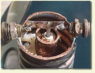
    The top of a stub will look like this when it is completed.
    Click for a closeup
    This is the top of a stub showing a BNC connector with the center conductor soldered (however crooked) to the thruline piece of copper strip then soldered to the center conductor of the Gimick Cap then terminating in the output BNC on the right. The gimick capacitor is inserted inside the center conductor of the hardline.

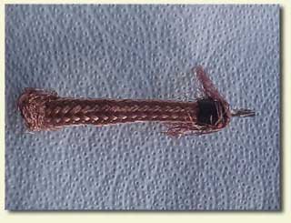
    This is how a "gimick cap" looks before being inserted into the stub.
    Click for a closeup
    I left a small ring of outer jacket on the braid for stability, this kept the braid snug on the inner dielectric and made insertion easier. The ring is on the top and bottom of the cap under the folded back sections of braid.
     
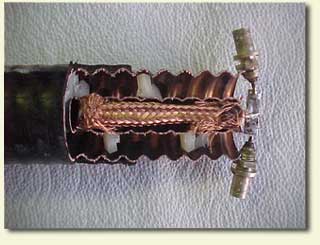
    This is how the whole assembly looks in a cut away view.
    Click for a closeup
    This is a good visual of the business end of the stub. You can see how the thruline piece connects to the gimick cap easily.

    Here is a description of how I tuned the duplexer and array.

    Here is a schematic diagram of the duplexer.

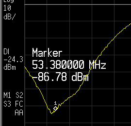
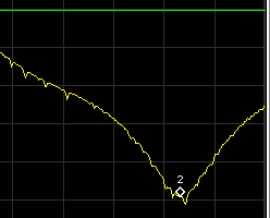
    Click-Click Click-Click Click to view full-size charts
    These are preliminary frequency responses of the receiver and transmitter legs of the Duplexer. These are without the Reactance caps installed and have not been final tuned yet. The receiver leg still only has 2 stubs as I have not built the third one yet.
     

    Now, I am still in the process of duplexing and tuning the radio as of 3/20/2003. The duplexer that I built needs to have the reactance caps and inductors added and the protective tops put on. I will include pictures when the final install is completed. The repeater is a hobby repeater and will be open to the local 6-Meter community. It will need tuning and tweaking as the radio is put on line and the process will take a few weeks I am sure.

    The function of this web page is to give a good visual idea of how the WB5WPA Duplexer looks as well as give some advice on building one.

    Summary of references from this page

    I am willing to give advice and encouragement to anyone who may be trying to build one. Please send me an E-Mail and I will gladly help however I can. I am hoping that this web page will inspire other Hams to build one, innovate and improve on the original design as well as put more open repeaters on the 6 meter band.

    73's
    Oscar Quintanilla
    KF6YB