Some Work Projects
This page is pictures and descriptions of some projects that I have worked for my previous two employers. Click on the pictures for larger image.
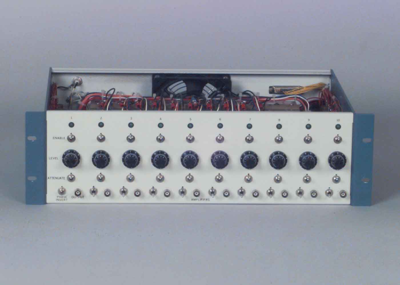
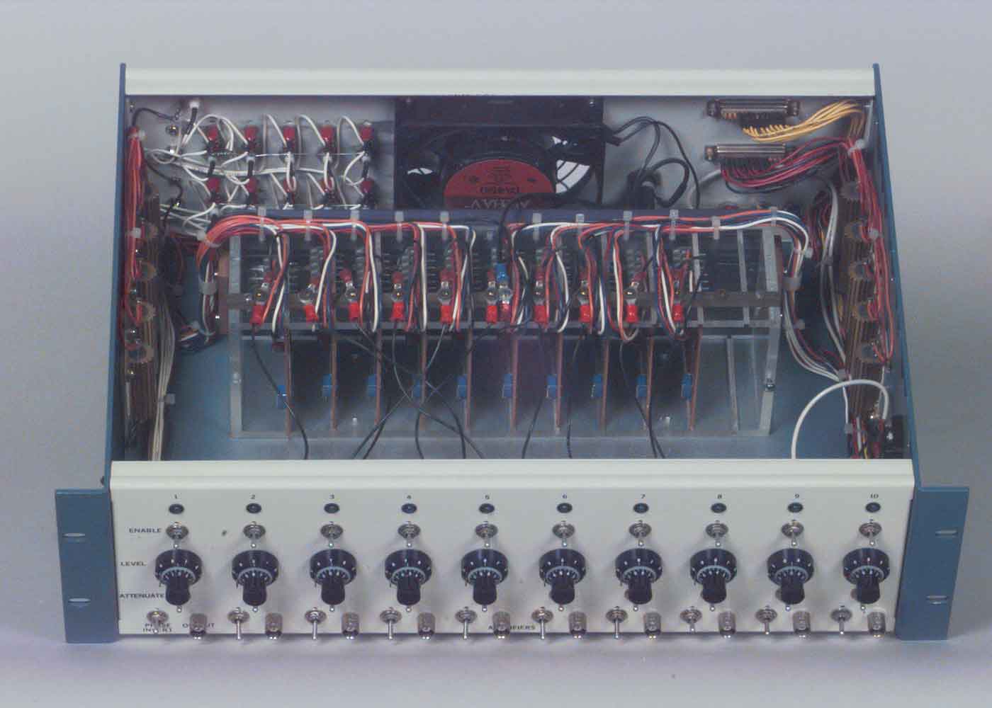
Ten Channel Amplifier
Design is based on National Semiconductor LM1875. Features include separate or bussed amplifier inputs, and each channel can be enabled from a rear panel connector.
|
Amplifier, front panel |
Amplifier rear panel |
|
Amplifier, inside view |
Amplifier board removed from card rack |


Thermistor Based Dual Thermometer
The hardware consists of two thermistor probes connected to conditioning circuits. The thermistors are driven with a constnnt current of 50uA. The voltage drop across the thermistors varies with temperature. Using some gain and offset, that voltage is scaled to the 0 to 5 VDC input range of the analog to digital converter. The ADC is an LTC1298 which is controlled by an 8052 based Domino(TM) Microcontroller.
An 8052 basic program (link to source text file) in the microcontroller provides calibration and measurement modes. To measure temperature a voltage is acquired by the ADC and is stored as an ADU (Analog Digital Unit) between 0 and 4095. The program then applies an algorithm to convert the ADU value back to thermistor resistance. That resistance is used in an equation that describes the thermistor response curve to calculate the temperature in Kelvin. Subtracting 273.15 results in Celsius.
The algorithm is developed using the characteristics of the thermistor conditioning
circtlits. First the ADU value must be converted back to voltage. The full
scale value at 5.0 VDC is 4095, so (ADU*5)/4095 will provide that. Next the
ADU voltage has to be converted back to the thermistor voltage drop. To scale
the thermistor voltage drop the conditioning circuits apply 1.082 VDC offset
and a gain of approximately 27. That part of the algorithm is (ADU voltage
+ 1.082)/ 27. Then that value for thermistor voltage is used to calculate
thermistor resistance by dividing by the thermistor current of 50uA. The complete
algorithm is:
Rth=((((ADU*5)/4095)+1.082)/27)/50* 10(exp-6)
The thermistor resistance is used in the formula T(K)=A2/(1og(R/A0)-A1 and
is converted to temperature is Kelvin. Subtracting 273.15 results in Celsius.
The thermistor curve formula comes from a thermistor specitcations handbook.
The values for the coeffiients are obtained in calibration. Calibration is
performed as follows: Matched sets of ADU values and corresponding temperature
are generated with the calibration section of the progrnm. The thermistors
are placed in a slowly heated and stirred beaker of water. The temperature
is obtained from a certified mercury thermometer. The operator enters the
temperature value and the program acquires the corresponding ADU value. After
the temperature is converted into Kelvin the resulting data is fit to the
thermistor curve using the Windows progrnm, Psi-Plot. The results are A0,
A1 and A2 coefticients that match each thermistor. These values are placed
the measurement section of the 8052 program.
|
Dual Thermometer, front panel |
Dual Thermometer, inside view |
Dual Thermometer, rear panel |


Coil set
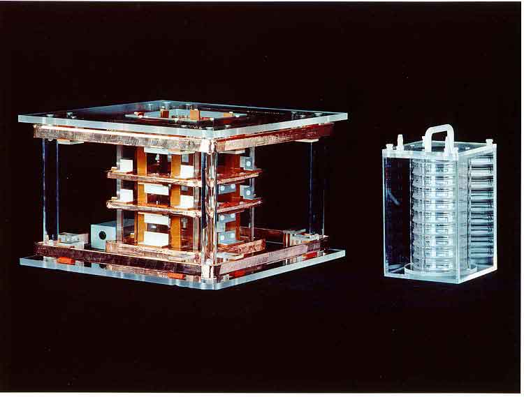
This coil set was designed by Dr. Maria Stuchly of University of Victoria. At left is the coil assembly and on the right is petri dish holder. The apparatus is used for exposing cell culture to magnetic fields. All the coils were wound with MWS Bifilar magnet wire, which provides field cancelling option. There are a total of six coils. The upper and lower inside pair are a Helmholtz configuration. The inside middle pair are called a Merritt set. The two outside upper and lower coils limit leakage to adjacent experiments.
Motorola Cellular Phone Study
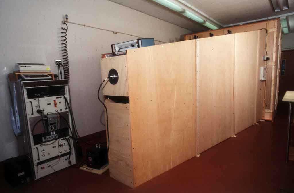
Far Field Equipment
The rack in the left picture contains a Motorola supplied signal source for the ~850 MHz mobile phone carrier, an RF Amplifier and a Watt Meter. Designed horn from Motorola specifications using DOS based CAD Program. Construction is of Luan plywood with copper foil glued to one side. The signal is fed into the horn where the round disk can be seen with a cable attached. Behind the disk is a crossed dipole antenna. The right picture was obtained by removing the panel at the feed point and taking a picture towards the exposure area
|
Motorola Far Field Exposure Horn |
Horn exposure area with cages in place |

Near Field Equipment
Left picture is of two level exposure racks. Each layer contains ten PVC tubes for restraining rats in proximity of a cellular phone antenna. The front of PVC tubes fit into receivers made of Lexan, and the right picture is a close up them. All the receivers fit on a larger 1/2 inch Lexan disk which is supported by the rack frame. Note antenna at center of right picture.
|
Near field exposure racks (two level) |
Center closeup of individual of one level |


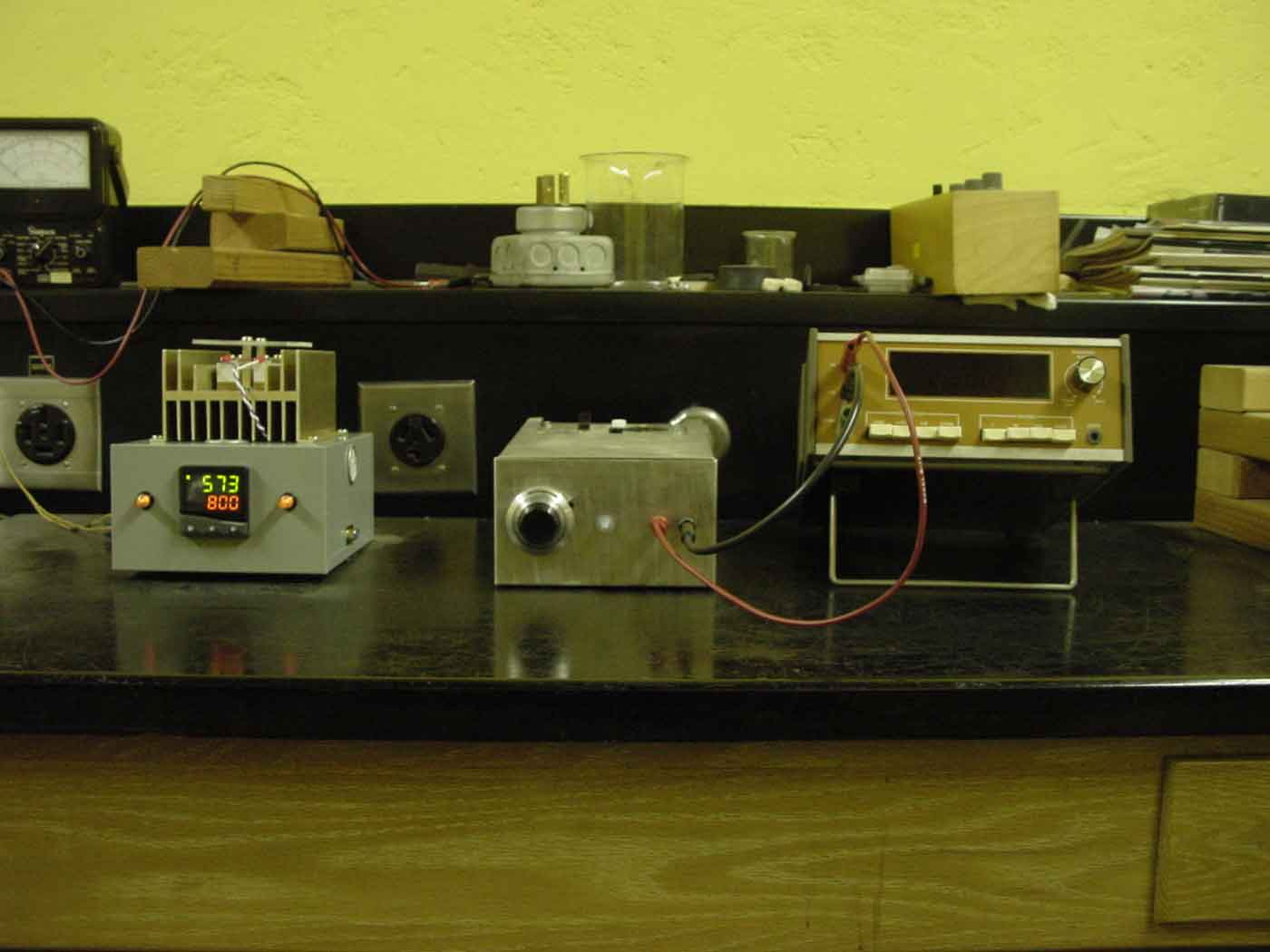
Tube Furnace Controller upgrade
This equipment is part of High Temperature Superconductor physics laboratory. Students fabricate a superconductor which they also test as part of the lab. The fabrication process involves two cooking cycles in a Tube Furnace that can reach 900 degrees C. The original furnace controller was based on the TDA1023, proportional triac trigger. Its major drawback was that ramp and soaks had to be done manually. A CN9600 series controller and solid state relay were obtained from Omega Engineering. The controller was mounted in a box along with a 220 Breaker, AC receptacle for the Furnace power, and a DB9 serial connector. The solid state switch was mounted on a heat sink on top of box. The controller interfaces to a computer through a serial port. A software application from Omega allows graphical programming of the controller through the serial port.
|
Programmable Furnace Control at left. Original manual controller at center (connected to bench DMM) |
Programmable Furnace Control, front |
|
Furnace Control, inside left |
Furnace Control, inside top |


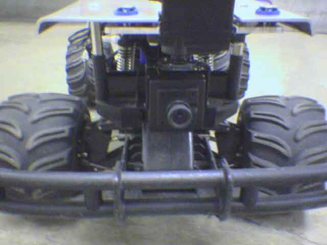
Rover Simulator
This RC vehile was used in an astromy lab to simulate some funtions a of planetary rover. A moderately priced Radio Controlled Vehicle was purchased. It turned out to have inadequate throttle or steering control. The original drive motor was adequate, but the speed control was upgraded to a Novak Rooster. Steering servo was replaced with one from an Airtronics VG600 transmitter kit (the original transmitter also had inadequate range). The Sony Color Mini CCD camera is mounted to a servo to move it left or right. Wireless Transmitter and receiver for the video signal were purchased from wirelessvideocameras.com.
 Rover, original camera mounting |
Rover, new camera mount detail |
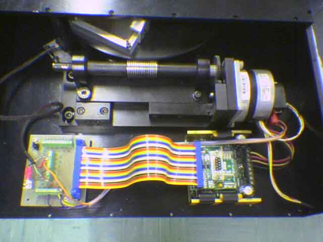
Polarimeter for 1m telescope
Below is inside view of one of two filter wheel drawers that are part of a Polarimeter Assembly used on the 1m Telescope at Table Mountain (near Wrightwood, CA). The bottom part of the wheel can be seen engaged in the worm gear on the shaft. The stepper motor is at right, and controller (model IM483IE) is at lower right. They are both both made by Intelligent Motion Systems. At lower left is interface board for home sensor and encoder connections. The Polarimeter also contained a linear stage and a rotating polarizer, but I don't have pictures.