Kenwood TH-G71A Modification Page
Posted 3/5/98. Mod info courtesy of Jerry, (KK6YO)
KENWOOD SUPPLEMENTARY Amateur Radio Division Asi-0036
SUBJECT: TH-G71A Beyond Mars MODIFICATION DATE: 11/03/97
This modification is provided "as is" and is subject to change without notice,
Kenwood Service Corporation (Nor I) make any warranty of any kind with regards to This
modification procedure, including, But not limited to, the implied warranties
of merchantabilty and fitness for any purpose. Kenwood Service Corporation(And I)
shall not be liable for any error or for incidental or consequential damage
in conjuction with the furnishing, performance, or use of this modification
procedure.
Modification procedure.
1 Remove The battery Pack and antenna.
2 Open the SPKR/MIC dust cover.
3 Remove the three screws from the back panel of the transceiver
4 Carefully lift up the bottom end of the back panel and pull the entire
back panel towards the bottom of the transceiver to clear the antenna
connector from The top pnnel. Do not break the ribbon cable That
connects the back panel PCB to the front case PCB.
5 Set the back panel to the left side of the front case.
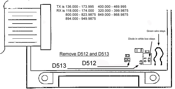
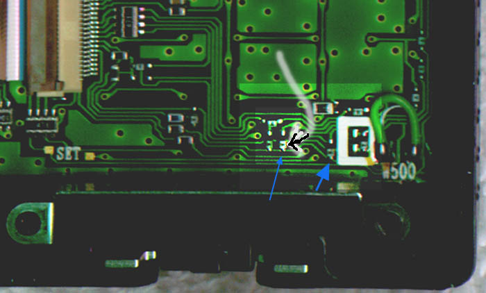
6 Locate and remove diode D512 and D513 from the bottom right side of the
front case PCB.
7 Assemble the transceiver by reversing the steps listed above. The
transciever will automatically reset when turned on.
TX Capability.
136.000 - 173.995Mhz 400.000 - 469.995Mhz
Rx capability.
118.000MHz- 173.995MHz, 400.000MHz- 469.995Mhz
320.000MHz- 399.99375Mhz, 800.000MHz- 823.9875Mhz
849.000MHz -868.9875Mhz 894.000MHz- 949.9875MHz
NOTE: This change also allows the transceiver to access a previously suppressed
menu number 16. this menu allows the transceiver to switch between FM and AM in
the ll8Mhz- 136.000MHz range.
Another Note: If you only want to expand the RX,Remove D512 ONLY.
For MARS/CAP TX expand only, cut the green wire(W500)ONLY.
P.S. Thank you to the people that sent me info about this. bb
Here is a drawing of the radio. (Which tells you just about everything you
need to know.)
Here is a picture of the radio apart just before I removed the Diode.
It is really quite easy.
The arrows point to the Two diodes that need to be removed.
"Do not attempt any of these modifications without checking all applicable laws
in your area. Doing so may violate laws and destroy your radio if you do not
know what you are doing. All such activites are done at your own risk. Content
of this page is for informational purposes only. No express or implied warranties
as to the accuracy of the information.(Or spelling!)" (There, my rear is covered : )
If you do not feel confident with very tiny, surface mount parts,
Click on the Banner or one of the links at the bottom of the page, and they will
be glad to help you arrange for them to do it.

Some Links To some Other Pages (Some do not work yet :( )
Angelfire - Easiest Free Home Pages
My Jeep (And Main) Page.
My Fire Department Page (Under Construction)
Click Here for KK6YO's Hamshop Featuring Mod and Install Tips, Ham radio products, and more!
AVVid is an Authorized Kenwood and Icom Service Center

Email: [email protected]