|
|
|
|
Since I got my license in 1993, I always dream up of a decent HF antenna that enables me to "chase" DX signals. But being a city dweller in the heart of the Silicon Valley make things extremely difficult for me to put up any decent antenna. In a way, I am luckier than most of my friends, I live in an "old" neighborhood where there is no CC&R. But my property location has the overhead high voltage power lines in the backyard at around 35ft, not much space on either side of the house and a large front yard so it is kinda awkward to install a "serious" antenna for HF work (unless I can convince my wife to let me put it up in the front yard!). Being a CW
person, I keep "falsely" telling myself that I don't really need a
good antenna to work DX in CW since CW can get through even during extremely bad
condition. So instead of improving my antenna situation, I keep augmenting my
city lot property with more low dipole and vertical antennas. As a result, the
roof of my house looks very much like a giant spider web with copper wires and
nylon ropes every where! The picture
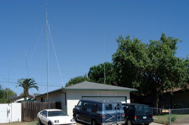
Here is the Butternut HF9VX vertical antenna attached to the side of the house (right at the front door! The XYL doesn't care as long as the antenna does not interfere with her flowers on the ground...)
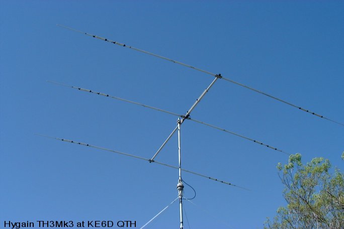
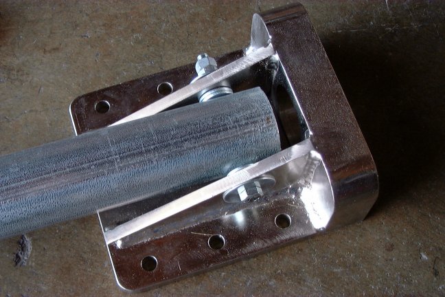
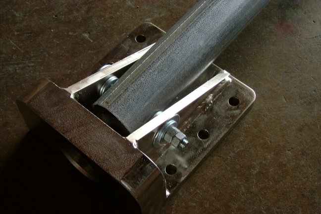
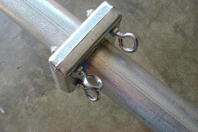
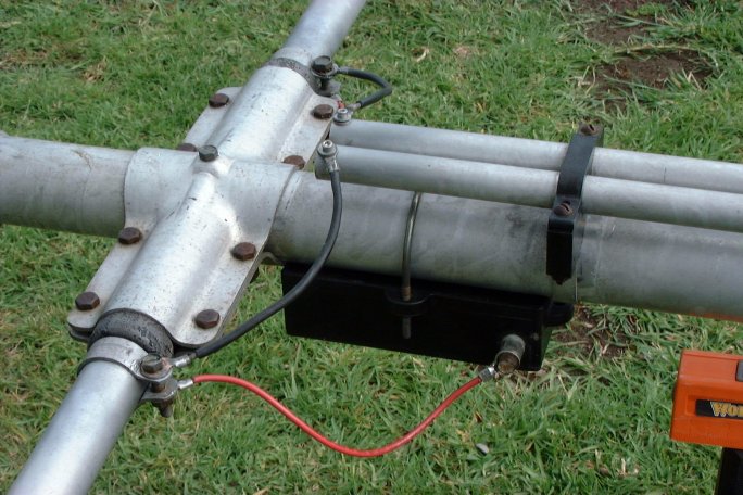
These antennas seemed to work ok most of the time, I was able to make plenty of contacts with many US and DX stations as long as the condition is good. But I must admit that there were times when I just wished I can hear the DX station a 'lil better so that I could tell that he was indeed talking to me... About four years ago, a local HAM upgraded his antenna to a Force 12 C4 and offered to sell his old Hygain TH3Mk3 and the Alliance HD 73-1 rotator system for about $100. I couldn't pass up such an opportunity so I drove to his house to pick up the TH3 and the rotator that weekend. He really did a superb job in dismantling the old antenna. He labeled every component of the TH3 with permanent marker and included a manual of the TH3 and the HD-73 in the package - Boy, what a good deal I'd got! After taking the TH3 package home, I quickly scanned all the components of the TH3 and its manual, I quickly put everything back into the carton, then moved the box into a corner of the garage because this antenna is MUCH MORE complicated (as far as assembling and erecting) than either a parallel dipole or a Butternut HF9V vertical which I am pretty much comfortable with at the time. The TH3 and the HD 73-1 rotator had been pretty much forgotten for the last 4 years! In the back of my mind, I knew that I would play with it one day, but wasn't really sure how I could put it up... In early Winter of 2001, after quite a few fail attempts work the DXpeditions in Africa with my dipole and vertical antennas, I decided to survey my property one more time trying to find a place for the TH3. The only place I may be able to put it up is right on the peak of the garage. The TH3 has to be mounted either on a heavy duty telescopic mast or on a roof tower configuration such as the one marketed by Glen Martin Engineering. My garage is not covered so it is quite easy to get up to the bottom of the roof and shore up the structure under the antenna mast and at the guy anchoring points. After talking to a few friends on a local repeater, I was pretty much made up my mind to go with a mast support structure since it would look esthetically nicer than a roof tower. The mast would sit right at the peak of the garage roof and would be guyed at the four corner of the garage at the 10 ft level. I would use 2 sets of guy wires (2 x 4) to secure the the mast in place. The idea is that one set of guy wires would serve a back up for the other set. This would allow me to work/repair the guys while the other set hold the antenna in place. But I still could not figure out how to mount a 37 lbs fully assembled HF Yagi antenna onto the 15 foot plus mast. The idea of tying a ladder (or 2) to the first 10 ft section of the mast so that two us can climb up there to attach the antenna doesn't entertain me very much since it is very dangerous. My buddy, Ori, AC6AN, suggested a mast which can be tilted down (like most roof towers) for antenna attachment, then a few of us can walk it up into the upright position while another person working on tightening the guy wires. As soon as Ori said the magic word, I knew exactly how I can build the mast and install it on the roof of my garage! This mast can be tilted down to the driveway to enable us attaching the Yagi antenna to it from a step ladder. The first step was strengthening the portion of the garage roof under the antenna mast base and the four corners of the roof where guy anchors were to be mounted. A short trip to the local Home Depot to pickup 2 x 6, 2 x 4 woods, guy hooks and couple hours later, the garage roof was ready!
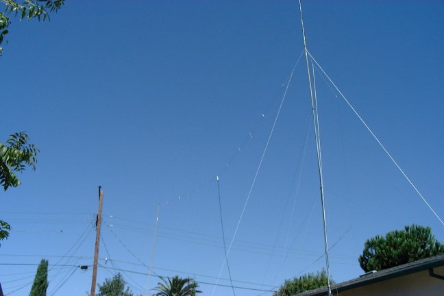
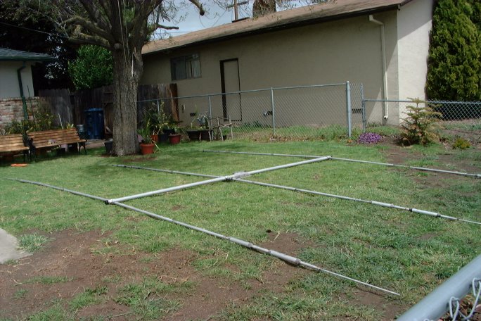
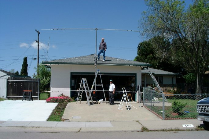
After the mast was built and antenna assembled, I kept waiting for a weekend with clear weather so that I could organize an "antenna installation party" with the help of my buddies from a local repeater club. But for some reason, the weather in northern California was very unpredictable this year. The rain were still pouring down even in late April, especially on weekends! I had to cancel the "party" more than once just because things looked so good during the week, but turned into rainy weather on weekend. I kept watching the weather patiently and hoped for a break in the storm pattern. The break came on Saturday, 4/21/01 (after I had called my buddies up to cancel the party the night before because of heavy rain on Friday!) Seeing that the sun came up really early and dried up all the rain water from the day before. There was also no wind! I decided to call up my friends to get the "party" started. Unfortunately, everyone already made alternate plan after I canceled the "party" the night before. Only Bob, W6KO and my brother in-law were available. Figuring out that I could erect the antenna with 3 people, I decided to go ahead with the installation.
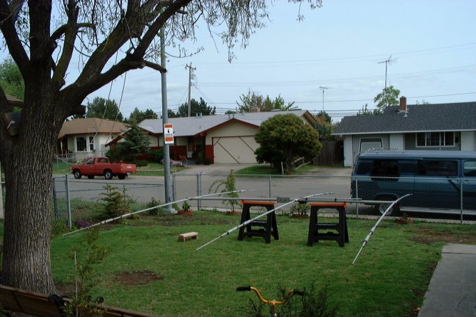
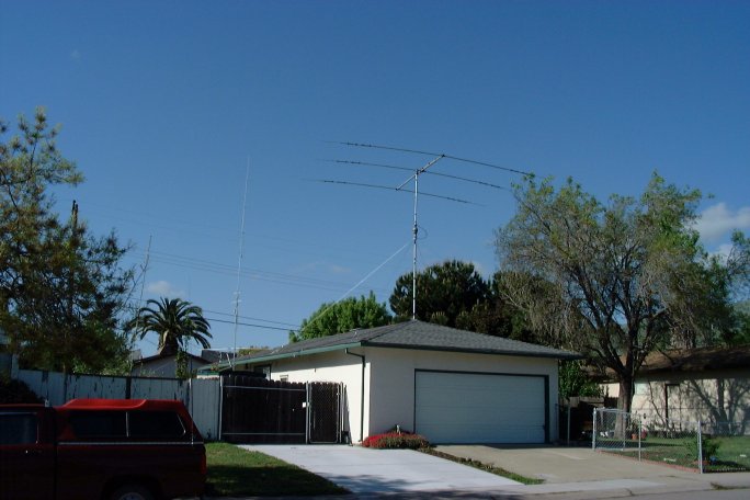
Things I've learned: Unlike dipole or vertical antenna projects, erecting an HF beam required a lot of planning. The more time one spends planning the installation procedure on the ground, the less time to think and work out a problem when the antenna is raised (believe me, the last thing you want to do is when the antenna is raised, then a problem comes up and you don't have an answer for it!) Due to certain physical restriction at my property, i.e., 4 ft wire fence in the front yard, power line in the back, tall tree on the side, I did spend quite a bit time thinking about solving these problems. That really paid off since I knew exactly what to do when it was time to assemble the mast, mast base anchor, guy wires and antenna. I was very happy how well things went together that day. Believe it or not, I am already working on my next installation which will raise the beam another 8 ft higher, exerting less load onto the rotator, and mechanically sturdier. So if the thought of improving the HF signal is in the back of your mind, may I suggest a small tri-band HF beam supported by a mast on the roof of your house. This antenna doesn't have to be very high. A rotatable antenna at a height of 30ft (~1/2 wavelength on 20M) will do wondrous job to your signal. You will be very much surprised to to find out how much better you can receive (and transmit) on this small beam vs. the old dipole or vertical... I worked J5X the other evening with just a couple calls... Needless to say, I am a very happy camper at this moment...
73 es Gud DX, Dan, KE6D
This page was last updated on 05/15/01 at 1554 PDT |