RockXcvr
40 Meter CW Transceiver

In an effort to construct a station I've built entirely myself, I turned my attention to a receiver. I first tried building a D-C (Direct-Conversion) set designed by the same crew that developed the Tuna Tin 2 (called The Herring Aid.) I didn't have much luck - probably from my inexperience with D-C design - so I decided to make one that was a simpler to begin with. I have borrowed ideas and designs from numerous sources, beginning with the MRX-40 published in QST.
For a good paper on DC Receiver design check out the one at Ocean State Electronics Download page: DC Receiver Design Notes and Problem Cures.
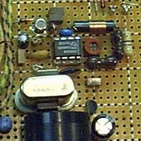
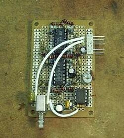
Receiver The heart of this project is the SA602 Gilbert Cell Mixer/Oscillator IC made by Phillips Semiconductor. With the addition of an input filter, a crystal, and an audio amplifier you're ready to go! I'm using a crystal "bender" using a MVAM109 variable capacitance diode varying voltage applied by a 10-turn pot. This gives me a -5 Khz tuning range from the chosen crystal. I have since built a VFO which I will experiment with implementing when I find a box to sheild it. |
 |
Low Pass Filter 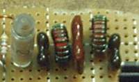 |
Initially I had problems from picking up the College FM radio station from their tower that is about 1000 feet from my shack. (They're on the low end of the FM Broadcast band.) I added a low-pass filter at the antenna input and diminished that considerably. I'm hoping that once I get it shielded in an enclosure it will eliminate it entirely. |
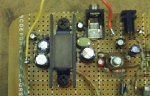
Audio Amp The audio stage uses the LM377 dual 2-watt amplifier IC (located under the heatsink) in a bridged configuration to drive the speaker with 4-watts. The LM377 is difficult to come by now, but I had one kicking around still in the Radio Shack "Archer" bubble pack (blue card) looking for a home.I'm using a 2N2222A for a preamp. |
 |
Transmitter 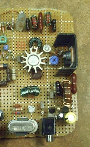 |
This is a 5-Watt design by Mike Martell N1HFX with a few modifications of my own. It uses the IRF510 Mosfet for output, 2N3053 for driver and I chose the 2N2222A for the oscillator transistor. A pretty straight forward design and he specs parts that are available at Radio Shack. (with the exception of the toroids and crystal.) I added a 78L09 to keep the oscillator voltage constant, and a 100W trimpot after the final transformer to adjust the output power. N1HFX suggests setting the IRF510 gate bias so the idle current is 5ma. I found the best performance from this MosFet at 3.5ma. I also added the few components he suggests to stabilize the IRF510 in his Rose-80 design (see part 3.) I've also done some modifications to the oscillator to help stabilize that. Great work Mike! Thanks for the assistance. |
CW Filter I've experimented with a few audio filters using op-amps as ~800Hz band-pass filters. So far, the op-amps only add more noise than they eliminate. Currently I've had good success with this design published in a 1988 issue of Rad-Comm which uses phase-shifting. I used TL072 low-noise op-amps and made it so I can easilly plug it in and out of the main board. |
 |
Enclosure
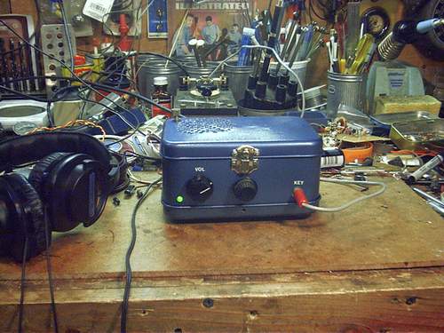
I found an old metal Pok-E-Mon collectors box at our local Goodwill which caught my eye as an enclosure for this. Primarily because it had a hinged top and bottom. This allows me to access both the top and bottom of the circuit board for modifications (which I am always up to) with out removing it from the case. By the way it did eliminate most of the College FM radio station interference when I installed it in the box. Unfortunately, adding a preamp before the LM377 increased the interference immensly. (I'm still working on this, but for the mean time I've bypassed the preamp.)