The heart of this tone board is the 567 Tone encoder/decoder. The common designation is NE567 made by Signetics, I had a number of XR567's laying around but don't look for one of those, Exar went out of business long ago. The one drawback to using this IC is that frequency adjustment is tedious and difficult to do on the fly, especially if the board is mounted inside. The three repeaters I want to reach all use the same tone so I'll set it there and forget about accessing any others for the time being.
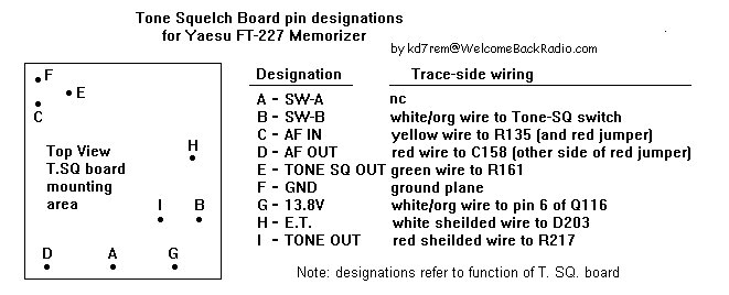
Here are the original designations for the tone squelch board used by Yaesu:
In order to use the Tone SQ switch on the front panel to activate the CTCSS tone I rewired the switch so that the front panel squelch control stays activated even when the switch is depressed. To accomplish this perform the following:
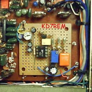
For constructing the tone board I used half of a Radio Shack (276-148A) Dual General-Purpose PC board. In order to make it fit in the space intended for the original tone squelch board, perform the following:
This circuit converts the square wave output from the 567 to an acceptible sine wave.
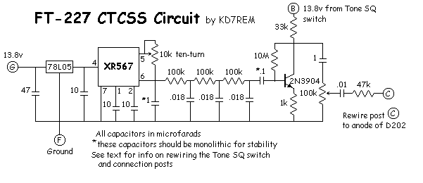
The level adjusts from 0 to 2 volts peak to peak. I adjusted the 100k pot to just under a quarter turn and it was enough to break the squelch of the repeater. Use a frequency counter to set the tone.