R-2000
Narrow / Wide Filter
Mod
Submitted by Frank
Cathell K3YAZ and Lou Blasco
This modification allows you to use the Narrow/Wide switch to select the optional CW filter position when listening on SSB or CW. It will not affect AM or FM operation.
This mod will not be very useful for those of you that already have the optional YG-455C filter installed. For the many of us that don't have the YG-455C installed, this mod will allow us to use the spare F2 filter position to experiment with various filters and test their effectiveness compared to the standard SSB filter.
"Why can't I just use a filter of my choice in place of the YG-455C filter and select CW?" I hear you ask.
You could but the results would be less than satisfactory. As noted elsewhere on this website, the R-2000 shifts the first local oscillator frequency when operating in CW mode. This means the centre frequency of the IF is 455.7KHz instead of 455KHz. With this mod you can use any filter with a centre frequency of 455KHz.
This mod requires a fair bit of effort to complete and you need to be handy with a soldering iron too.
THEORY
For those of you with a circuit to refer to, a quick look at the schematics will show you how the R2000 selects the filters. If you don't have a circuit yet, get one from elsewhere on this site. On the RF board there are two connectors that are involved in the selection of the desired filter. Plug 42 (Pos F6) and Plug 35 (Pos H3). It is these two connectors that carry the control voltages responsible for switching the different filters.
Plug 42 brings control voltages from the PLL board to the RF board. These control voltages (around 9 volts on my radio) select the different detection modes (AM, CW, LSB, USB). We'll forget FM at this time.
They also feed two control control voltages (AMB and CWB) to Plug 35. Plug 35 leads to the narrow/wide switch on the front panel.
Take a look at the circuit for the narrow/wide switch S24. It is shown in the wide position.
The filters are controlled by the application of a positive DC control voltage to turn them "on". There are three selectable filters:
All right. Lets
trace the circuit for each mode.
AM - Start with S24 in the wide position
On plug 42 AMB goes high all other control voltages are low. AMB on plug 35 goes high, AMW plug 35 goes high which in turn applies a control voltage to R97 hence filter F4 is selected.
If we switch to narrow, AMW on plug 35 goes low and SSB on plug 35 goes high which then applies a control voltage to R92—hence filter F3 is selected and filter F4 is now off.
CW - Start with S24 in wide position
On plug 42 CWB goes high all other control voltages are low. SSB on plug 35 goes high which in turn applies a control voltage to R92—hence filter F3 is selected.
If we switch to narrow, SSB on plug 35 goes low and CWN on plug 35 goes high which applies a control voltage to D55—hence filter F2 is selected and filter F3 is now off.
How many of you have wondered why you can't hear anything on CW only to find you've accidentally selected the narrow position on the filter switch? Now you know!
SSB - Start with S24 in wide position either LSB or USB.
On plug 42 either LSB or USB goes high all other control voltages are low. These feed either D35 or D36 which in turn apply a control voltage to R92—hence filter F3 is selected.
If we switch to narrow, nothing happens because both AMB and CWB on plug 42 are low.
The Modification
About an hour of work and the addition of one diode should see this done. If you get a YG-455C filter some time in the future you will have to reverse this modification and take out your extra filter.
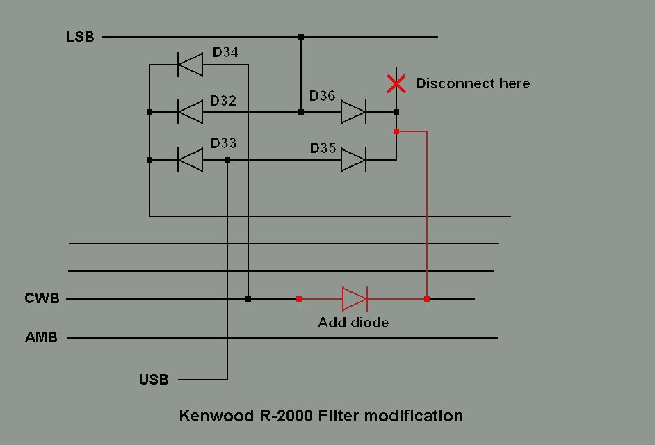
With the bottom cover removed and the front of the unit facing you locate diodes D35 and D36 near the edge of the pc board next to the front of the radio. Unsolder and lift the cathodes of both diodes and join them in mid-air to a short length of hook-up wire around an inch long.
Now, below the diodes (closer to the board edge) are two short, horizontal jumpers that are electrically in series. Remove the left jumper and replace it with a 1N914 or 1N4148 diode with the cathode side to the right. Mount it in a "hairpin" fashion so the anode end is in the left hole and almost touching the pc board. The cathode end should loop down into the right hole.
Now connect the other end of the hook-up wire from D35, D36 to the cathode of the newly installed diode.
The modified circuit is shown below.
The modification now means that CWB on plug 35 will be active in CW/LSB/USB mode. Switching between wide and narrow will select SSB or CWN respectively on plug 35.
When switching from either sideband to CW the 455KHz IF will be shifted up 700Hz. The filter selection will remain unchanged. Switching between wide and narrow will select SSB or CWN respectively on plug 35.
In AM mode the narrow wide switch selects 2.7HKz or 6KHz.
Suggestions, comments, corrections or additions may be emailed here.