
Interfacing a Maxtrac, Maxtrac 50, Maxtrac 100, Maxtrac
300, Radius M100, M214, M216, mobile to a repeater
controller
Remember, above all, that these are MOBILE radio, and while it can be used quite readily as a receiver, you cannot use it as a repeater transmitter or link transmitter without due consideration to the normal mobile radio limitations on RF power and duty cycle.
That said, the radios that have the 16 pin accessory connector on the back of the radio can be programmed via RSS to supply all the signals needed for both a repeater receiver, or as a link / repeater transmitter. Pins 4, 6, 9, 8, 12 and 14 can be assigned in the RSS.
Yes, radios with sixteen pin logic boards are easier to use in a repeater or link environment, but the cheaper radios with the 5-pin logic boards can be used with minor modification. The major limitation of 5 pin boards is that you have to bring out the COR/COS signal by adding one resistor and one transistor, and you can only program one input signal (perhaps transmit PL inhibit) and one output signal (perhaps PL decode). Five-pin boards are quite usable in repeater service (especially as link radios or fully-PL'ed control receivers), after all, who needs a 16 or 32 channel radio for a single channel application like a dedicated repeater or link use?
Really, the cost difference between a 16-pin radio and a 5-pin radio is worth an hour or two of bench time. There are three versions of the 5-pin board. The modifications to these allow you to perform the following.
- 1) Do all of the interfacing through the mic
jack
- 2) Use etch cuts and jumpers to reassign four
of the 5-pin accessory connector pins (one pin is
ground)
- 3) Unsolder and remove the 5-pin connector (or just cut away the plastic around the 5th pin - the ignition control sense pin) then unsolder it. Then route a short pigtail cable out the opening, with a DB9, DB15 or some other popular connector on it. Having a pigtail connector allows any signal you want to be brought out, on any pinout, and you can keep the front panel mic jack available for a local microphone. It's a bit more work, but it is the most flexible.
By the way, if you put 16-pin firmware into a 5-pin board you can program pins 2 and 3 on the 5-pin connector (normally associated with emergency input and alarm output) for other functions just as if they were pins 9 and 4 on a 16 pin board if you have one of the better 5 pin boards. Further info on the logic boards is presented in another article here.
The microphone jack on a MaxTrac has a 560 ohm input impedance and a resistor from a filtered positive voltage source to provide DC to the MIC audio input pin to power the preamp that is internal to the microphone cartridge of a Motorola microphone. Because of the preamp, any audio source fed to the microphone jack will require a considerably higher level - on the order of 100 to 300 millivolts for full deviation. If your external equipment isn't giving you that much when connected to the radio, then you need to do something to make it do that.
Radios With 16 Pin Logic Boards:>
All the connections will be made via the 16 pin accessory connector, as shown in the following picture for both receive and transmit applications.

View looking at the radio accessory connector, bottom
of radio down.
By the way, the exposed pin on the power connector is
the positive pin.
You may find a jumper on pins 15 and 16 to enable the speaker, either as a physical jumper plug in the connector, as a PC style 2-pin jumper in the connector (as shown above), or as a jumper wire or as a solder blob inside the radio (this is covered later in the text).
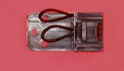
The above photo is of the official MaxTrac jumper plug: the top jumper is between pins 15 and 16 to enable the internal speaker. The lower jumper (pin 9 to 7) grounds the alarm input pin (e.g. forces it inactive no matter how the radio is programmed). The holes in the tab are for a tie-wrap that goes through them and around the cable jacket as strain relief.... outer holes for fat cable, middle hole and one outer hole for smaller cable.
The accessory connector shell part number is Digi-Key Part Number 104422-1-ND, made by AMP Corporation as their part number 104422-1. AMP makes a wide variety of contacts for this shell with varying wire sizes and plating types. The one most appropriate for 22 AWG wire is Digi-Key Part Number A3007-ND ( AMP 1-87309-3) And these pins are gold plated!
Pins 4, 6, 8, 12 and 14 on the 16-pin connector can be programmed in a variety of ways, including as repeater controller interfacing connections. On a radio that is new to you do NOT assume that any pin programming is present, or if it is there, is correct for your environment.
For a pin-by-pin dissertation of the 16-pin connector you can go read The Definitive Guide to the 16 pin MaxTrac and Radius Option Connector on the Repeater Builder website.
In most cases the transmit radio will be using
pins 3, 7, 2 or 5, and perhaps 6.
The receive radio will probably be using pins 4, 7, 8,
and 11.
Either radio may have a wire on pin 10, called
"Ignition Control", an option that allows the radio to
be controlled by the ignition switch. If the radio is
set up for this option, it will not power up unless
this pin is jumpered to +12v.
To get to the RSS screen shown below you must first read the radio, then from the main menu hit F4 for the Change/Create/View menu, then hit F2 for the Radio Wide menu, then hit F9 for the Other Accessory menu.
Note from WA6ILQ:
I suggest that you read this write-up completely and as you do make notes how you want to program your radio(s). I also suggest that if your application requires two radios (one for transmit and the other for receive) that you combine the programming and set both radios the same (i.e. add transmit PL Inhibit and timeout timer disable to the receive radio) and then use that programming on both, leaving one / half of each radio idle. Also make any hardware mods (i.e. adding the COS transistor to a 5-pin radio) on both. This allows you to have instant backup radios - if one radio dies you can simply exchange the radios to get the system back in service, and you can swap out the half-dead radio with a good spare later.
Here is the configuration for the receive radio: Note that in this write-up pin 4 is the carrier squelch logic level and pin 8 is the PL Decode ANDed with Carrier Squelch logic level (but there are several options on programming, and the pins can change). You can find the ground signal on pin 7. Receive audio appears on pin 11, and depending on an internal jumper you can have it be in either of two modes: 1) de-emphasized and squelch muted or 2) flat and unmuted. A photo of where to find the jumper is on this page. Too bad you can't get a third option: flat and muted. You can also get 300mv of de-emphasized audio at the top of the volume control or on the handset earpiece pin of the microphone jack.

The terms Active High and Active Low for the "Active Level" options in the RSS can be misunderstood, resulting in major confusion. Active Low means that the pin is normally floating, and is pulled to ground when the function is true. Active High means that the pin is normally pulled to ground, and is allowed to be pulled high when the function is true. Either mode requires an external pull-up resistor to work properly, and you may find the pull-up is internal to the radio or an inherent feature of the external circuitry or device.
Configuring the transmit radio: Some folks trust their repeater controller's internal timeout timer, others like having a second one further downstream in the PTT path as a backup. Those in the first group can disable the timeout timer (program it to a value of 00), those in the latter group can program it to any value that the radio supports.
Either way, you will probably want to enable one very useful setting: transmit PL inhibit, which can be used to disable the internal PL encoder by grounding the appropriate pin. This allows your repeater controller to turn it on and off remotely. Even if you don't use it immediately, it's probably worth programming now and reserving that pin on the connector for future use.
Here is the RSS screen for the transmit radio. Here we are setting pin 7 as transmit PL inhibit. Transmit audio goes in on pin 5, and PTT is on pin 3.

Just use the enter key to move around, it will highlight each item as its selected and you use the up and down arrows to change each selection. All the functions can be set for low or high. So if you need an active low or active high COS/COR just set it here and you are done, no radio modifications or hardware changes are needed to go from one to the other. This is why the 16 pin radios are more desirable, everything can be done via RSS to match the controller being used.
Note from WA6ILQ:
If your repeater controller has a similar active low or active high choice you should find out which is the idle state (i.e. if there is nothing hooked to the controller's input pin, what does the controller idle to?). In the case of the inputs on the SCOM 7K the idle state is a high signal, so I program the controller to an active low, and the Maxtrac to an active low. If I need to power down the Maxtrac control receiver the controller can continue to service the other radios in the rack since the powered down Maxtrac looks like an inactive port.
The only other thing you need to do is decide on PL decode. You will probably leave the receiver in carrier squelch and let the repeater controller handle the mode change from Carrier to PL Decode using the two signals provided. If your controller is overly simple and has only one input (yes, there are those out there) you can wire it to pin 8 and use an output from the controller to ground or unground the "Hook" lead on the microphone jack (pin 3 - ground is on pin 4). With pin 3 floating the monitor light will come on and the radio is in carrier squelch mode. With pin 3 grounded the monitor light will go off on the front of the radio (i.e. PL decode is on). If this does not work then check in the RSS Radio Wide menu that off hook PL/DPL is set to "N" for no.
If you want PL decode to always be on, and have no need to remotely disable it using the repeater controller then just make a jumper plug to put in the mic jack with pins 3 and 4 connected (this is useful on PL'd links). You can also go the Radio Wide menu and set Off Hook PL/DPL to "Y" for yes. This keeps the PL decode on regardless of hook state on pin 3, but PL decode can still be turned off by manually pushing the front panel MON button.
Note from WA6ILQ:
IRLP systems do not have separate PL and COS inputs, they have only a COS input, but have three AUX outputs. I suggest that you wire the IRLP COS input to radio pin 8 (ground is on pin 4), and wire one of the AUX outputs to mic jack pin 3 to allow you to remotely select between carrier (floating) and PL mode (grounded). Or if you want or need some isolation between the radio and the computer, just use the AUX output to flip a reed relay, and the contacts wired to the mic jack pins 3 and 4.
Radios With 5 Pin Logic Boards:
The stock 5 pin connector has the following
pinout:
(pin 1 is nearest the edge of the chassis - i.e. the
right side of the above photo)
1 - ground
2 - emergency alarm in
3 - external alarm out
4 - external speaker audio out
5 - ignition control sense input
The ignition control option allows the radio to be controlled by the vehicles ignition switch. If the radio is set up for this option, it will not power up unless this pin is jumpered to +12v.
As mentioned above, if you put 16-pin firmware into a 5-pin board you can program pins 2 and 3 for other functions just as if they were pins 9 and 4 on a 16 pin board.
An alternate way to interface a 5-pin radio is to remove the 5-pin connector from the logic board and use the hole in the heat sink for a pigtail cable with a DB-9 or DB-15 female on it. Or you can cut the plastic body of the connector between pin 4 and pin 5 with a sharp knife and unsolder/remove pin 5 and that will leave enough space for a thin multiconductor cable to exit the radio.
Or if you want to leave the radio intact, the simplest repeater controller connections can be done using the ground, earpiece audio out, microphone audio in and the two extra pins on the front microphone jack. This also makes it fast and easy to swap a malfunctioning radio.
Since the 5 pin logic boards are not capable of being programmed for all the signals needed a minor modification is necessary to bring COR / COS out - in this case to either pin 1 or pin 2 of the mic connector. The following modification will give you a low going COR / COS using the audio mute signal from the CPU. By the way, pin 1 of the mic connector is located on the top end of the connector (nearest to the volume control). Note that 900 MHz MaxTracs have the components that implement HearClear (a noise reduction technology based on a compandor circuit) mounted on the microphone jack / volume control circuit board in the control head.
To add a COR circuit to a MaxTrac the only parts needed are a 10k resistor, and a common NPN transistor, for example a 2N2222 or a 2N3904. In the text and drawings below this new transistor is called Q1, not to be confused with any Q1 in the radio.
First thing you need to do is disassemble the radio. This involves removing the Torx head screws, two each side, and the two holding on the front panel. Remove the front panel first and then remove the bottom cover. With the front panel facing you look for the radios CPU, left half of the board towards the rear of the radio.
There are several varieties of the 5 pin logic board and there is a slight difference between the Radius M-100 and Maxtrac radios as well. Refer to the two following pictures showing the CPU and connection locations for the two varieties.
Connect to the locations as shown here in the following picture depicting a Maxtrac HLN9123A (the most minimal logic board).
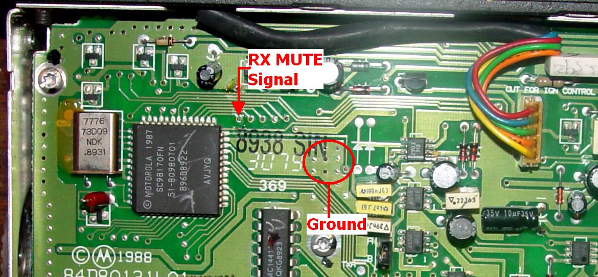
You need to remove the solder masking from the through hole for one end of the 10k resistor. Solder the other end to the base lead of Q1. Remove some of the solder masking from the board's ground plane and solder the emitter of Q1 to it, keeping it above the board slightly. Just like building dead bug style. The floating collector lead will be used in the next step.
Note from KBØNLY:
If you want a Positive aka High going COR just connect the collector to a source of voltage in the radio I like to use pin 5 of the rear connector which is ignition sense and powered to B+ when the radio is on. Use a pull-up resistor or a small pico fuse inline with pin 5 and the collector. Then run a jumper from the emitter to J8.
Note: Before making the connection to J8 leave the front panel connected and verify with an ohmmeter that you have a connection from pin 1 of the mic connector to a pin on J8. As said above, on the 900MHz radios the pin 1 and pin 2 mic jack pins never leave the front panel switch board and you will have to tap onto pin 1 or 2 there.
Then from the collector of the new transistor run a small gauge wire to J8, pin 1 of the mic connector is on pin 8 of the J8 header, counting right to left with it oriented as shown in the picture, pin 2 of the mic connecter is on pin 9 of J8. COR will now be available on pin 1 or pin 2 of the mic jack. Until now both pin 1 and 2 of the front panel microphone connector is unused.
For RX radios the connections are as shown in the picture below.
The "RX Audio" shown above on pin 8 was originally intended as handset earpiece audio, and the level is unaffected by the front panel volume control. It works just fine as de-emphasized repeat audio out (i.e. audio going to the repeater controller).
For transmit radios the connections are as shown in the picture below.
Another way of looking at the mic jack is:
1 - unused, but fed to the logic board *
2 - unused, but fed to the logic board *
3 - PL defeat (a.k.a. the mic hook switch)
4 - ground
5 - microphone audio in
6 - PTT in (ground to transmit)
7 - SCI+ (bidirectional programming lead - used by the RIB for programming the radio - leave this floating)
8 - handset audio
* only on the low band, high band and UHF radios... on 900 MHz radios the two unused pins never leave the front panel board.
There is a "Flat audio" input on the 16-pin radio accessory connector. If you compare the schematics of the 16-pin board and the 5-pin board you can see how to dig into the circuitry and inject audio into P6 pin 13. A spare pin on the mic jack can be used for this, with an appropriate DC blocking series capacitor, and perhaps a audio level adjustment potentiometer.
As with the 16 pin radios you can select PL decode or CSQ by grounding or floating the hook switch line on pin 3 of the mic connector. Refer to the 16 pin directions above for further info on that. Alternatively there is a PL decode signal available inside the radio that can buffered with another 10K resistor and transistor, and fed to a spare pin on the mic jack. Just compare the 16 pin and 5 pin schematics.
A big THANK YOU is due to Robert W. Meister WA1MIK, for providing screen shots and photos.