
Triangle Gasket Fractal Antenna
![]()
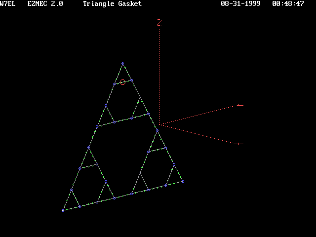 3rd
Order, Triangle Gasket
Due to the high volume of wire consumed in this design, it was necessary to enlarge the frequency range to ascertain
any finger print for the form. The feed point was moved through the design to find patterns resonances. All such
points were chosen with bilateral symmetry in mind. Thus the SWR charts below illustrate the drive condition found
for the chosen feed point. Again, given the amount of wire consumed in this design, frequency points of 5 MHz intervals
are used below. This makes for a rather jagged presentation and may even result in hiding sharp resonances.
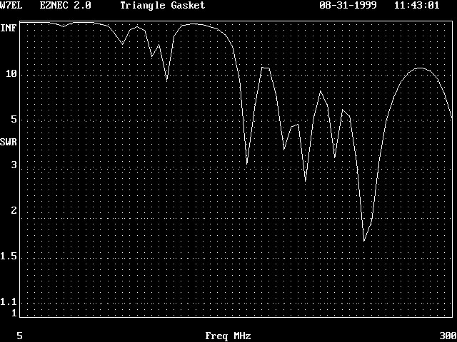 This is the SWR for a 200 Ohm feed point Z. The feed point corresponds to the source being inserted
at the top corner (a V-like configuration). This is an extremely Hi Z antenna with the majority of resonances
at 600 Ohms or more.
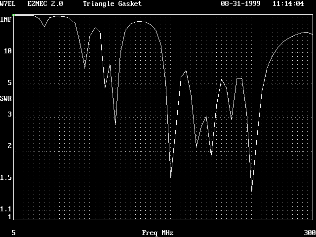 This is the SWR for a 200 Ohm feed point Z. The feed point is found as illustrated above. It is different
from the other interior feed point responses in that its lower frequency components are truncated or lost (like
the corner drive above).
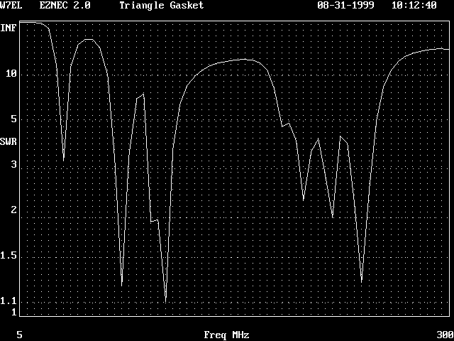 This is the SWR for a 200 Ohm feed point Z. The antenna is in fact even more resistive, ranging from
300 - 400 Ohms. This SWR is not due to the drive point illustrated above, it occurs on the horizontal wire immediately
below.
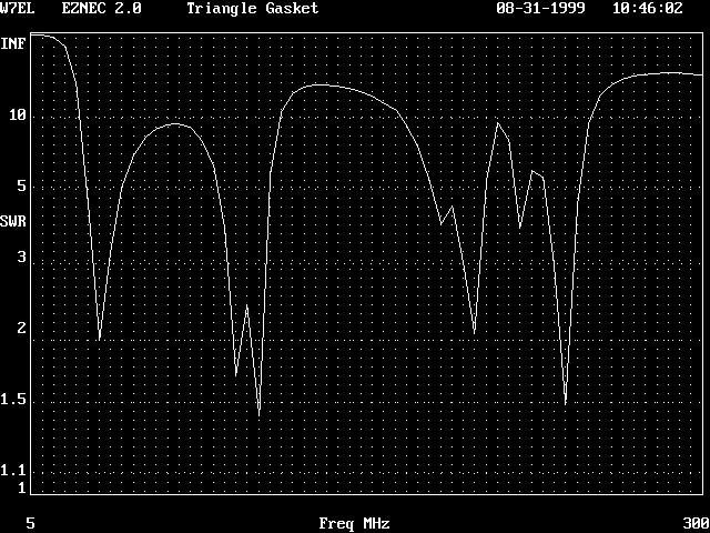 This is the SWR for a 200 Ohm feed point located at the bottom wire (dead center). Large non-resonant
regions match other data. Null depths vary, but their resonant frequency appears to remain constant.