The Discone Antenna
This antenna is often implemented in a skeleton form. Small, UHF forms may be constructed of sheet metal and thus exhibit the distinctive Disk and Cone.
 This is the
basic form for a 16 spoke, Discone Antenna. The cone section below the disk will have the cone apex angle changed
in a suite of tests. What appear below are Smith Chart snapshots of the characteristic Impedance of this antenna
through the iterations of changing the cone angle from 20 degrees to 90 degrees. The cone angle for the antenna
illustrated here is 60 degrees. This angle is very typical.
The length of the cone side is 0.25 of the wavelength of the lowest frequency of interest. The Disk, or Top Hat,
diameter is roughly 0.175 of the wavelength of this same, low frequency. These two dimensions are approximate and
should be approached with standard caution (although they are easily within the suggested dimensions of many authors).
More care should be considered in the gap of the disk and the cone. The cone can never come to an absolute point
(the coax center conductor has to emerge, unshorted, somewhere), and there are compounding issues of construction.
This will take more than standard caution, but reasonable solutions have been shown in the literature. Expect to
have to adjust the separation of these two regions by up to 1 foot for HF applications (40 to 10 M). I will repeat
at this point that it is conventional to bring the transmission line up beneath the cone to the open apex. The
shield should be connected to the cone section and the center conductor is passed through the open apex to the
disk section.
The Smith Charts below will display a very different characteristic compared to other antennas. The resonances
of this antenna are distinct, but very broad. For certain configurations, these nulls begin to blend. The Data
speaks for itself.
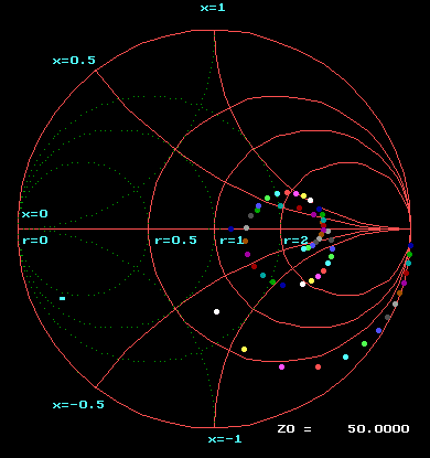 |
20 Degree Apex Think of this as a beach umbrella being opened beneath an already open parasol. However, before we begin to open that umbrella, the skirts are the closest to the mast as they will ever be. The Smith Chart is read from the 3 o'clock position where the data points start sweeping frequency from 1 to 30 MHz by 0.5 MHz increments. The data spirals clockwise into a circular knot. Observe how over the iterations of opening the cone angle also unwinds this knot. |
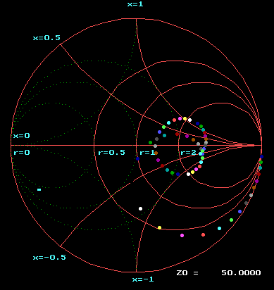 |
30 Degree Apex The first step change of 10 degrees in opening the cone's apex angle. The rotation of the knot for the 20 Degree Apex is clear. It is the limb of frequencies 20..30 MHz that is unfolding. It is lifting up from the lower frequency, primary loop. |
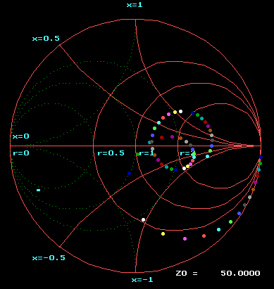 |
40 Degree Apex That limb has uncoiled from the knot to leave the primary loop behind. The primary loop will now begin to predominate in the change of this structure. |
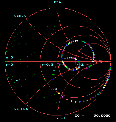 |
50 Degree Apex The limb is developing into a secondary loop with a growing radius. |
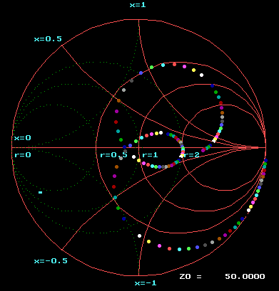 |
70 Degree Apex The primary loop is beginning to uncoil at a slower pace than the growing secondary loop being pulled counter clockwise. |
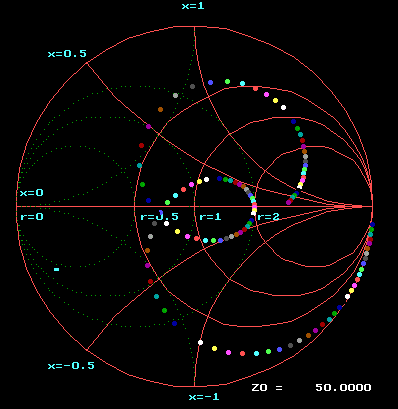 |
80 Degree Apex The primary loop's rate of growth is beginning to match that of the secondary loop. However, both appear to be slowing in growth. |
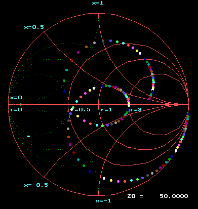 |
90 Degree Apex This is about the optimal antenna of this series for the number of points filling the 2:1 SWR circle. |