The SW for the PIC microcontroller is based on a method described by Terry Weeder "Remote Control Adapter", Electronics Now - August 1995. Most commercial handheld infra-red remotes can be used with PROgramit IRext since the PIC microcontroller can "learn" the codes produced by your remote. Here is how:
If you hold down S1 while powering up the circuit, the interface enters the program mode. Do not hold the key for more than 2 seconds because the RA4 input is programmed to an output to light the LED 2 seconds after power-up if the SW detects S1 down during that time. At this point the SW expects you to first press the remote's "Volume Down" key and then the "Volume Up" key. The LED will momentarily go out each time a signal is received. Then, press buttons on the remote in the order in which they will control the keys on your scanner. For example, figure 1 is the PROgramit setup screen for my PRO2032. Remember that this screen shows how I have wired PROgramit to my scanner, not the way the keys appear on the front panel. The next key that I would press on the remote is the one that I want assigned to "SPEED". The LED blinks to indicate that a signal was received. The next key I press is the one that I want assigned to "SCAN". I continue across the rows and down the columns until all buttons are assigned. If there are less than 64 buttons on my scanner or on the remote, I press the button assigned to "SPEED" repeatedly until I have pressed a total of 64 buttons. At this point the interface is programmed and it enters the run mode. Pressing the buttons on the remote now cause the interface to send the appropriate switch close, switch open commands to the scanner. The LED blinks to indicate that a valid signal was received.
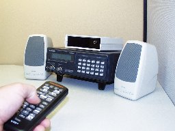
The audio volume can be controlled remotely if you connect your scanner's headphone output to the audio input of the PROgramit IRext interface and a speaker to the interface's speaker output. Output volume to this speaker is controlled by the Dallas Semiconductor DS1804 digital potentiometer.
Schematic Diagrams
|
|
|
Circuit Description
The circuit is based on a preprogrammed PIC 16F84 microcontroller.
The IR signal is detected by an LT1060 IR detector module. This unit produces
an unmodulated TTL output from the modulated 40Khz IR signal. Similar modules
are available from Digi-Key for remotes that use other modulating frequencies.
All of the info that I have read on IR indicates that 40Khz is the most
common. Please refer to http://falcon.arts.cornell.edu/~dnegro/IR/IR.html
for information about IR encoding methods.
The preprogrammed PIC micro is available from me. This part is reprogrammable to give us the flexibility to add new features and do any necessary tweaking without tossing it and burning a new one. In the program mode, the micro measures the durations of 32 high/low pulse combinations for each button press and stores these in the 93LC86 EEPROM memory. This will produce a table of thirty two unique entries in the EEPROM. In normnal operating mode, the micro measures the durations of 32 high/low pulse combinations for a button press and compares the string of measurements against each table entry in the EEPROM. When it finds a match, the index into the table indicates the X/Y switch in the CMOS switch matrix that is to be closed. For exanple, if the received string matches the pattern of the 2nd table entry, Y0,X1 (SCAN) is closed. If the third entry is a match, the Y0,X2 is closed (MANUAL). The micro must delay long enough between closing and opening a switch. In the PROgramit software, you have control of this duration using the delay factor. I have preprogrammed a duration here that I think will work with all of the supported radios so far. I will need some help at first confirming this.
The external version uses a 74ALS541 to buffer data before it is sent to the PROgramit PARALLEL interface OR a MAX233 to drive RS-232 compliant signals to the PROgramit SERIAL interface. Install one or the other. Install a jumper in J1 to ground pin 7 of the RS-232 connector ONLY for serial operation.
Power can be from a 12V DC wall wart power supply. Current draw is less than 50mA. Place C7 as close as possible to IRD1 and C3 as close as possible to the VCC pin of U2.
You should not have to use S1 often, so you could replace it with jumpers on the board that can be momentarilly shorted.
Item Qty References
Value
------------------------------------------------------------------------------
1 1
S1
SPST Pushbutton (Optional for programming mode)
2 1
R1
1K ohms
3 5
C1,C3,C6,C7,C8
0.1
4 1
C9
1uF
5 1
R6
2.7 ohms
6 1
R2
470 ohms
7 1
R3
7.5K ohms
8 1
S2
SPDT (Optional for RF/IR feature switch)
9 1
SPKR
SPKR
10 5 C2,C11,C12,C13,C14
0.1uF
11 1 C15
100uF
12 1 C10
470pF
13 1 U6
LM380 (8-PIN Version)
14 1 RX1
RX433 (Optional for RF feature) (TechAmerica)
17 1 P1
325F-ND
19 1 D1
LU20341 (Any LED)
20 1 U5
74ALS541P (PARALLEL OUTPUT ONLY)
21 1 IRD1
LT1060-ND (Digi-Key)
22 1 U4
MAX233CPP-ND (SERIAL OUTPUT ONLY)
23 1 U3
NJM7805FA-ND (7805 5 volt regulator)
24 1 C5
100 to 470 uF
25 1 Y1
X902-ND (4Mhz) (Digi-Key)
The following items are available from me only as
a kit for $16.00
26 1
U7
DS1804-050
27 1
U1
93LC86/P
28 1
U2
PIC16F84-04/ND (preprogrammed)