A few "inside shots" of some of the classic sets during repair and
restoration sessions.
This photograph is the undersides of my Hammarlund
HQ-129X, taken during an overhaul session in 1996. Note that ALL of the
original waxy paper capacitors have been replaced with newer, smaller
and less leaky (electrically and physically) poly or mylar capacitors.
In this particular unit, only a few resistors had drifted out of tolerance
and had to be replaced.
When I became the owner of my Viking II, it was discovered that the audio
was highly distorted at any modulation level. Once inside, it was apparent
that a previous owner had attempted to install his particular variant of
any of the many "audio modifications" that seem to proliferate among users
of vintage transmitting equipment. I chose to strip the audio circuitry
down to the chassis and restore the configuration to the factory stock
for the later model Viking II's. This photograph illustrates the audio
section of the chassis after teardown, while checking the driver
transformer for continuity. The one modification that was left alone
was the addition of the slider equipped power resistor, visible at an
angle in the upper right. This allowed (nearly) independent adjustment
of the final amplifier and modulator screen voltages, permitting a higher
level of modulation to be utilized.
This photograph is a classic example of what you
can expect when you locate an apparently clean and complete piece of
vintage gear at a hamfest priced well below what you estimate to be
the usual market value. This Ameco TX-62, nearly mint on the outside,
had obviously suffered some major distress undersides..a (non) living
example of the "Tune for Minimum Smoke" theory.
If you are into vintage ham radio, sooner or later you will probably own a
Johnson Matchbox, which was available in KW and 275 watt models. This is a wide
range tuner designed to handle balanced open wire fed antennas, but it can also
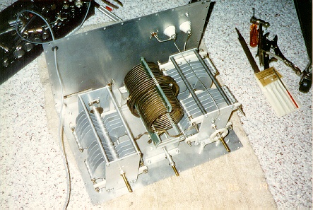
match single wire or coax fed systems as well. This picture is the innards of the
Nye Viking version of the Kilowatt Matchbox, which uses the same components as the
original Johnson, although in a more modern cabinet.
The resonating capacitor is visible on the left, with the heavy duty link
coupled band switched inductor in the middle. The differential capacitor
on the right is what provides the wide impedance matching range of this
tuner design.


 Comments are always welcome!
This page last updated December 24, 1998.