A note about my digital camera: It's an old Kodak DC120. I got it free, so I can't be picky. It seems to have a problem with over exposing pictures, and doesn't take very good close up shots.... well, whadda ya want for nothin'. Anyway, this is my excuse for the "less than perfect" images on the site.
June 16, 2002
I have completed the layout as a Powerpoint presentation, using the
same board dimensions as the 2N2/40. So
far, I have the AGC completed, and I found a couple of small mistakes in
the layout I created. Once I get this completed, and all of the errors
in my layout fixed, I will post it here for anyone that cares to use it
/ improve on it (definitely possible).
Per Chuck Adams', K7QO, website, I bought the hand sheet metal punch from Harbor Freight (item #44060). What can I say but, wow... what a difference. The pads that come out of this thing are great. If you are going to do any kind of Manhattan building, you need to get one of these things.
June 25, 2002
The VFO section is complete. The
tuning is quite linear and I am getting a spread of 5.0 to 5.080
MHz. The p-p voltages are somewhat higher in value from the ones
printed in the RH20 manual. I'm not terribly concerned about this.
So far, these new 1/8 inch pads are very nice to work with.
I can space them very close to one another, which saves valuable component
real estate.
Now, on to the receiver stage.
July 4, 2002
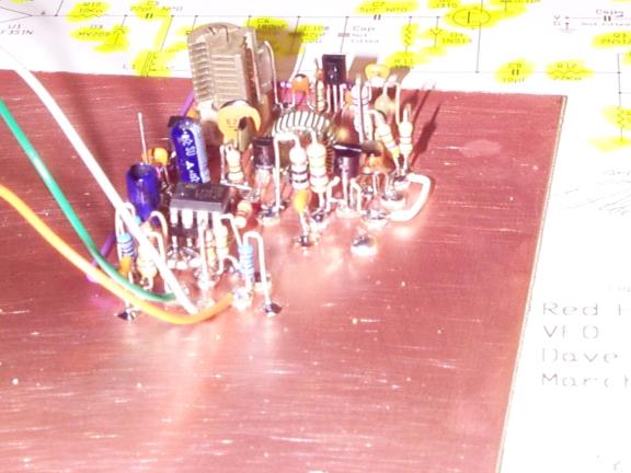
The receiver front end is completed
and working. The Red Hot 20 schematic calls for a Mini Circuits TFM-2
diode ring mixer. Dropping one of these in seemed too easy, so I
decided to roll my own. I used 4 1N5711 hot carrier diodes for the
diode ring, and 10 turns trifilar on each of the FT37-43 cores. If
you would like more details, drop me a line. I connected the front
end to the input of my IC-736 and tuned to 9MHz and.... at first nothing.....
so I started peaking the trimmer caps in the front end.... ahhh... that's
more like it. Beautiful sounding CW. The front end works.
Time to finish the receiver.
July 13, 2002
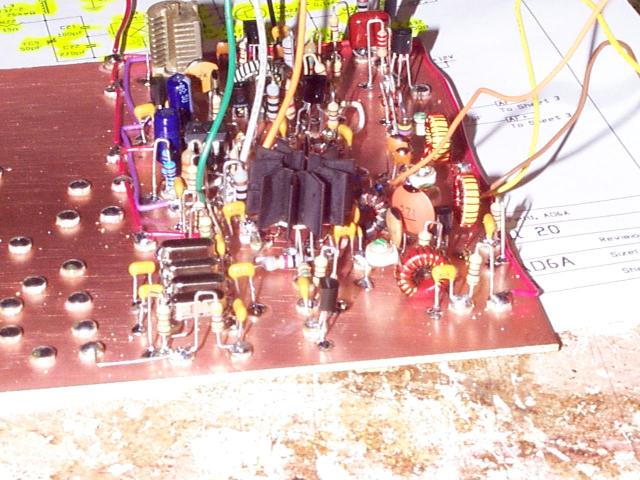
The receiver works beautifully.
I learned a very important lesson though. Series crystals are NOT
the same as those with a load capacitance. I found out the hard way.
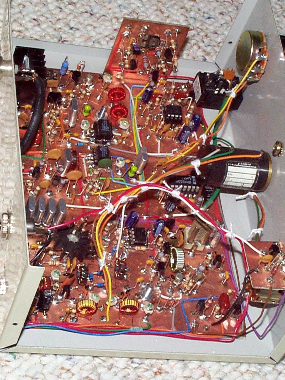
If you notice, the crystals in the photographs of the front
end and the finished receiver
section are not the same. When I finished building the receiver,
I couldn't get much out of it. I did some measurements with my scope
and found I was loosing the vast majority of my signal in the crystal filter,
and the magnitude of the 9MHz oscillator on the SA612 was much lower than
it should be. I looked up what kind of crystals I had ordered.
They were series crystals.... good chance this is the problem. I
trucked on down to my favorite surplus place here in Dayton (Midwest Surplus...
these guys are great!) and picked up the right crystals. Out with
the old, in with the new ..... and presto.... the receiver is performing
beautifully. Lesson learned here.... avoid series crystals.
I'm going to investigate this more and report my findings... seems like
a good topic for QRP-L. The small circuit board you see in the picture
is the AGC circuit. When the time comes to put the radio in an enclosure,
I am going to mount it with standoffs over the audio section.
Now, on to the transmitter stage.
Crystal Update: I ran the crystal problem I was having
up the flagpole on QRP-L and here is what the experts had to say :-)
| Mike - WA8BXN |
| The capacitance you see listed is the amount expected so the crystal will be on the right frequency for your circuit. VXO's vary the capacitance in a circuit the change the frequency and if you have a fixed circuit and want the crystal to be on a specific frequency that amount needs to be known to make the right crystal. My guess on what happened with your first batch of crystals is that they were so different in frequency that that range of frequencies each passed on to the next did not overlap so nothing got through. You may have seen notes some time ago here on matching sets of crystals for filters. You may have had a very un-matched set! |
| Dave Fifield - AD6A (This was an archived message in response to the same question I had) |
| The only difference between series and parallel resonant crystals is
the frequency for which they are cut. A series resonant crystal
is cut to the specified frequency such that it will oscillate at that frequency with no parallel loading in circuit. A parallel resonant crystal is cut such that, when it is loaded with the specified parallel capacitance, it will work at the specified frequency. Thus, a parallel crystal can be used in a series resonant application just fine, but it will oscillate higher than the specified frequency since there will be no parallel loading. How does this help you? Well, for crystal filters, the only thing that you need to worry about is that the crystals you use are matched to each other very closely. Therefore, for your scratch built SST, you can order *any* crystal type you like (as long as it's somewhere near the intended IF frequency of course!). You will have to order more crystals than you need and then select the 4 or so (not sure how many are in the SST crystal filter, sorry) that are the closest matched. You measure them by making them oscillate in a simple circuit and measure the frequency of oscillation of each crystal, then you select the ones that are closest together. A rough rule of thumb is that the crystals need to be within 1/10th
of the width of the crystal filter of each other. So, for example,
|
New lesson learned...... match the crystals in a crystal filter.... The new ones are matched now. What a difference it makes!
July 20, 2002
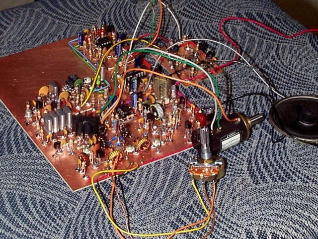
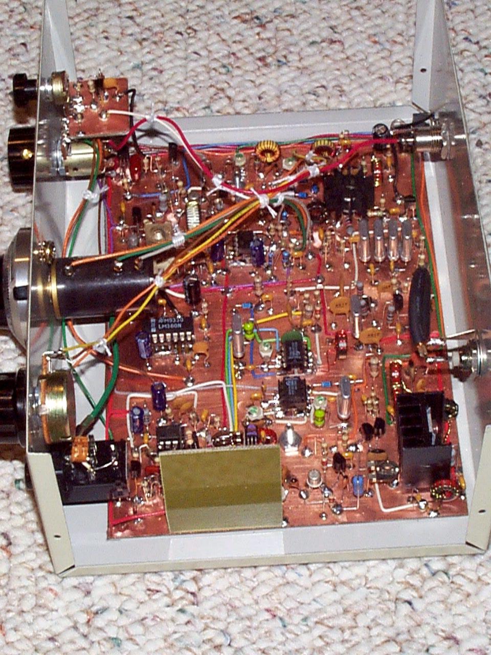
The transmitter section went together flawlessly. You will notice
in the photograph of my progress
that there are a lot of wires hanging around. I can assure you these
will be cleaned up prior to installation in an enclosure. I tuned
it up and set the output to 4 watts into my dummy load. Then came
the real test... an attempt at an on air contact. I heard Paul, W2TFL
in Walton, NY finishing up a QSO with another station, so I gave him a
call. He came right back to me... and gave me a 579. Not exactly
DX from Dayton, OH, but... it works.... and on an old 5BTV with 1 (one)
ground radial. There isn't anything special to remark about how the
transmit section goes together... everything went very smoothly.
Now, on to the RIT control and enclosure.
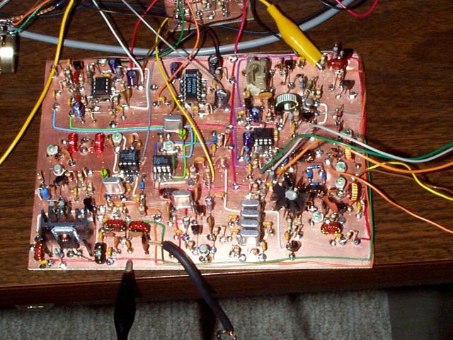
August 8, 2002
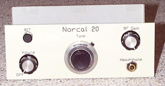
It's done! I must say that I am very impressed with the design.
The receiver is very sensitive, and there is more than enough transmit
power available. The RIT circuit causes no detectable VFO shift at
either end of the control. I used a 100K center detent pot that I
retrieved from an old VCR. The only change I had to make to the circuit
was to increase R6 and R7 from 33K to 330K.
Check out the photos and let me know what you think.
Front Panel
Close up of the inside (big)
Another close up of the inside
(big)