K7FJ BALANCED AUTOTUNER PROJECT
So far so good. The tuner has passed through the plywood and ceramic breadboarding strip phases
and is now built into an aluminum structure that holds all of the pieces together in what will be the
final physical configuration. The control and relay driver circuits are on double sided printed
circuit boards. The front panel switches and aluminum you see here are from the junkbox ... not very
pretty but servicable enough for testing. Dimensions are a little less than 8 inches wide X 9 inches
deep X 3 inches high (20 X 23 X 7.6 cm).
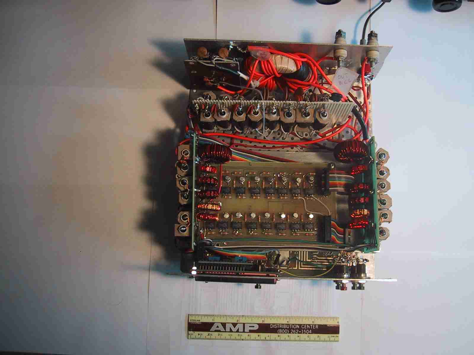
At the back of the tuner you can see the large toroid balun. To the left of the balun is the sensing
bridge for the SWR measurements. The capacitor switching matrix is just in front of the balun. The two
inductor switching modules are arranged on either side of the tuner along the left and right edges of the
tuner. The circuit board between the inductor modules holds all 16 relay drivers.
The large controller circuit card is mounted underneath the drivers in a shielded compartment next to
the bottom of the tuner. Part of it is visible just behind the front panel.

The tuner is in daily use now and when I am satisfied that no more major changes are needed I will build it into a new Elecraft K2 case with switches that match my K2 transceiver.

The tuner is designed to handle at least the 100 watts that my K2 can put out and I hope that it can handle
up to 500 watts during those rare times when the linear is needed. Earlier testing of the capacitor and inductor
modules at 500 watts showed no detectable heating when used with my 160 meter horizontal loop antenna but it
remains to be seen if the higher power will cause interference to the digital controller circuits.
I have not yet installed the antenna switching relay. If I need to be able to reverse the tuner to be able to
tune low impedance loads I will add a relay for that as well. My diagram shows that antenna #2 will be untuned because
my second antenna at this location does not require tuning. However, I will probably wire the antenna relay so that
antenna #2 is tuned as well so that the tuner will be more adaptable to new situations.
I have not yet programmed the tuner for full autotuning because there is just not enough EEPROM space remaining
in the Basic Stamp BS2SX to hold the code. As presently built there are two sets of switches to increase or decrease
inductance and capacitance manually. The tuner senses transmit frequency and when L and C settings for minimum SWR
have been determined all I have to do is press the Mode switch for at least 500 milliseconds to cause those settings
to be stored in EEPROM at a location appropriate for that frequency. Thereafter, whenever the tuner senses RF at
the input it will measure the frequency and make sure that the appropriate settings are switched in automatically.
I have found this system to be so convienent that I may never get around to buying a more capable PIC controller module
just so that I can have true autotuning. All I do when changing bands is press the Tune button on my K2 which
produces an output of less than 20 watts. The tuner then switches instantaneously to the correct values of L and C.
 BACK TO HOME PAGE