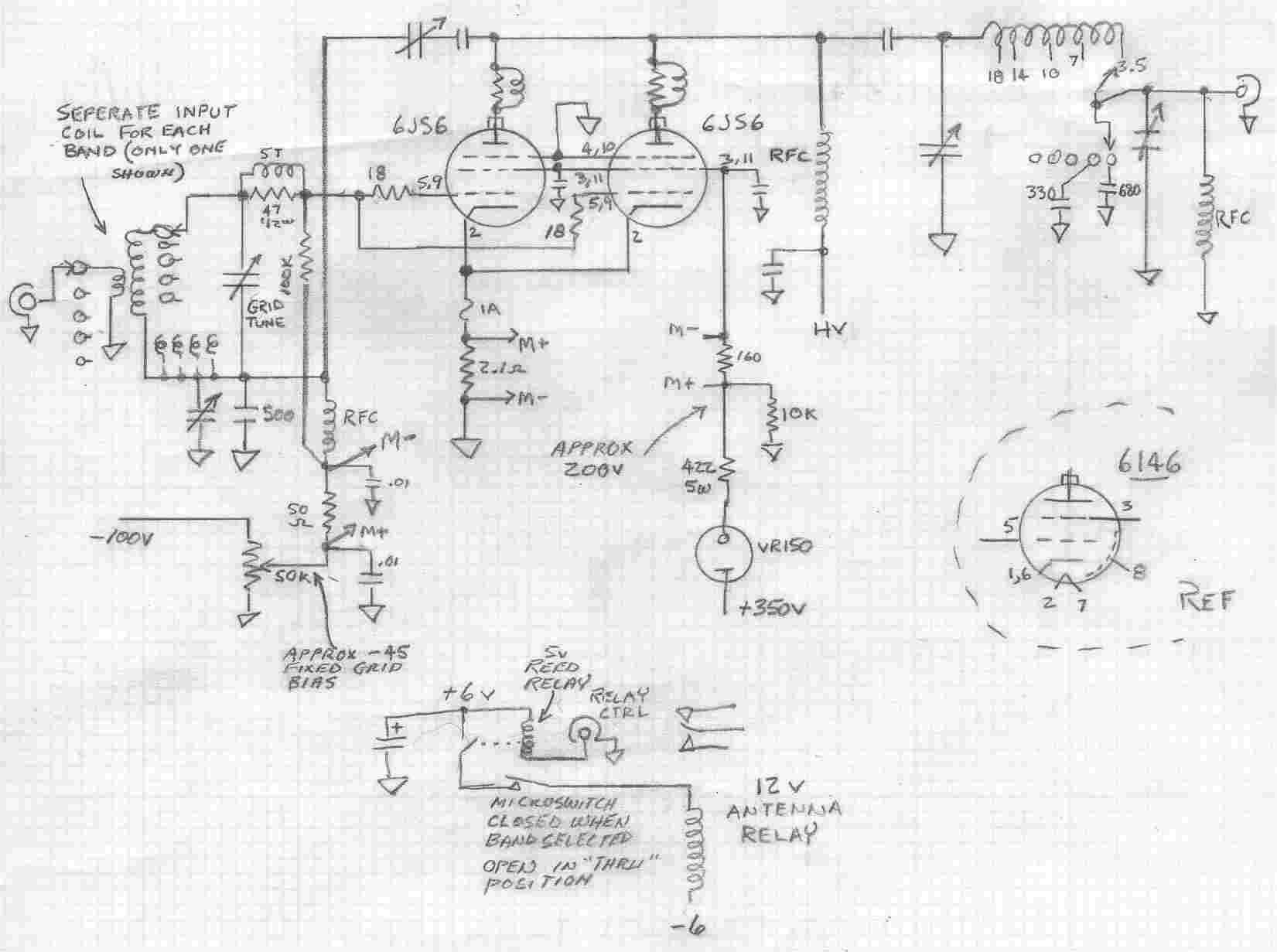
The schematic for the linear is very similar to that of many of the transceivers of the 70's and early 80's which had tube finals.
Mine originally had 6146 finals but I have replaced them with a pair of 6JS6's only because my pair of 6146's were in poor condition and I happened to have a pair of 6SJ6's
that were still strong and well matched.
The linear is based on a design in the 1961 ARRL Handbook "A 90-Watt All-Purpose Amplifier." The only significant changes I made are
that I used a pair of 6146's instead of the single one shown in the handbook and the component layout
is different only because of the particular chassis I happened to have on hand for it. Also, I already had
a suitable external power supply so I did not build one onto the amplifier chassis. Mine uses seperate input coils instead
of the custom coil assembly shown in the handbook. Mine is bandswitching (using two switches) for 80, 40, 30, 20, and 17 meters and puts
out over 100 watts easily.
The drive power required is less than 2 or 3 watts.
 BACK TO HOME PAGE
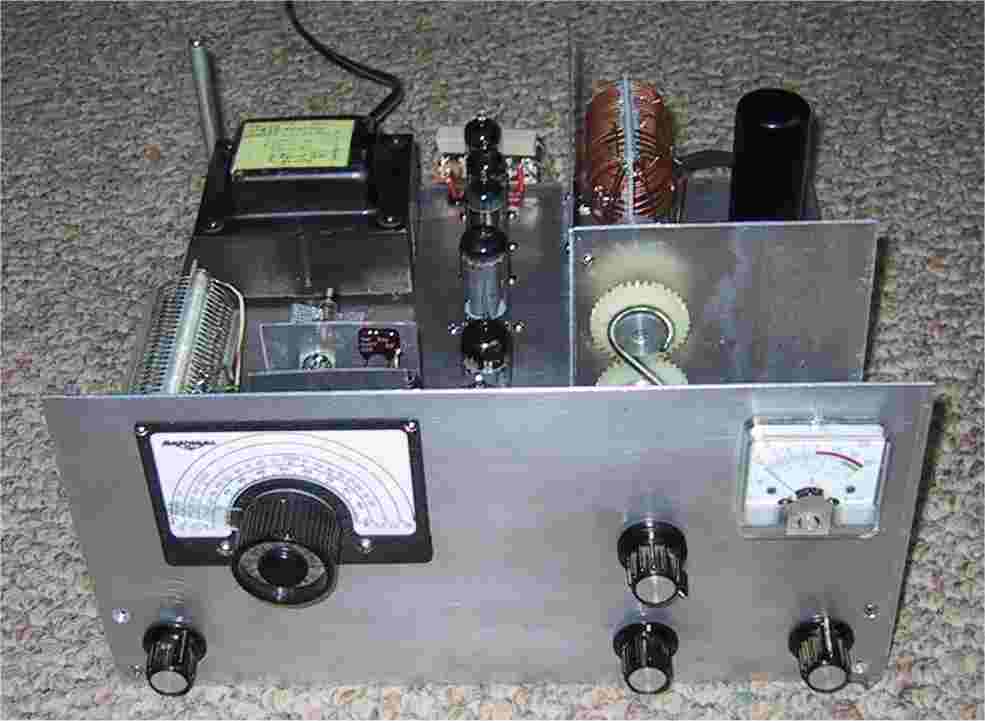 NEW QRP RIG