
PIC-EL Parallel Port Adapter
April 16th 2004
When the AMQRP Club announced that they were going to kit a board for PIC development, I just had to have one as I was just starting a project for the PIC16F84A. It seemed like it would be a lot cheaper and easier than rolling my own development board or buying a commercial one. The PIC-EL kit comes with everything to begin developing your own software on, and at a VERY reasonable price. It even comes with a nice LCD display, LED indicators, mechanical encoder, a speaker, and a port for the DDS Daughter Card.
Once I had it built and running correctly, I had no problems burning programs into the PIC16F84A from my main PC that has a built in RS232 Serial Port, but quickly found out that the USB to RS232 Serial adapter that I had for my Dell Notebook wouldn't work. I think that it's more of a USB Device Driver problem than a hardware issue. So, I searched the web for a possible solution. I could buy a PCMCIA card serial port adapter, but they are not cheap. I even found a web site with plans to take an old PCMCIA 14.4 Modem and convert it into a serial port, and I thought about doing this, but don't have an old modem. So, I figured that the easiest solution would be to set up the programming software (FPP) for a parallel port programmer and convert the TTL Levels of the parallel port to RS232 levels (+/-10 VDC) for the PIC-EL. I just happened to have a couple of TI MAX232N chips in my parts collection from another project, so thought I'd give this a try. The MAX232N is a 2 channel RS232 Line Driver/Receiver chip that does exactly what was needed, converting RS232 levels to TTL levels and vice versa. The MAX232N also makes a nice buffer to go between the PIC-EL and the PC's Parallel Port.
The total parts count is only 17 parts including a connector for the serial side and 1 for the parallel side. There are 10 caps, 2 resistors, 1 PN2222 transistor (used to pull the parallel port ACK line low) and the 2 TI MAX232N chips. I built the entire circuit on a little piece of circuit board from Radio Shack. Power for the circuit can be taken directly from the PIC-EL or another +5 VDC regulated supply. What I did is to connect two alligator clips to some hookup wire and soldered them to the GND and VCC lines on the adapter circuit. Then the alligator clips can clip onto the GND (TP-D) and +5 VDC (TP-C) test points on the PIC-EL to power the Parallel Port Adapter. Click below for the schematics of the adapter (Adobe PDF format):
PIC-EL Parallel Port Adapter Schematics V1.0
Once you have built the adapter and verified all connections (watch out for capacitor pollarity!) hook it up to +5 VDC. Check between GND and pins 2 and 6 on the MAX232N chips for V+ and V-. You should see around +8 to +10 VDC on pin 2 and -8 to -10 VDC on pin 6. If you don't, go back and check your wiring, you probably made a mistake somewhere. Once you have checked the wiring and you are sure that the voltages are correct you can hook the serial port side up to the PIC-EL and the parallel port side up to your PC.
Setting up FPP
The next step is to set up FPP for the parallel port instead of the serial port. I'm assuming at this point that you have installed FPP and have a basic understanding of how to set it up. If not please go to the Elmer 160 web page, download and read lessons 10 and 11 which give detailed instructions on downloading and installing FPP.
Launch FPP, and once it is open click on the "SETUP" button. You should see a screen pop up similar to below:

First set the hardware to "PARPIC" for the Parallel Port. Next pick which Parallel Port you want to use on your PC. Then select the device as a 16F84 if you haven't done so already. Next is the timing window. These are the settings that worked on my 1.2 GHz PIII Dell Notebook. The timing is slowed down a bit from my desktop machine (i.e. bigger numbers) and I think this is due to the much faster CPU in my notebook. FPP is an older program, so I don't think that it can handle the timing on a faster machine without doing this. On my main PC the timing settings were as listed in the Elmer 160 lessons and it worked fine with the adapter. My main PC is much slower though, a 550 MHz PII. Anyway, these timing setting work great on the notebook, so if you have problems on a fast machine try adjusting your timing to these settings.
Now, before you click the "OK" button (we're not done yet), click on the "Define/Test" button. You should see a screen like this:
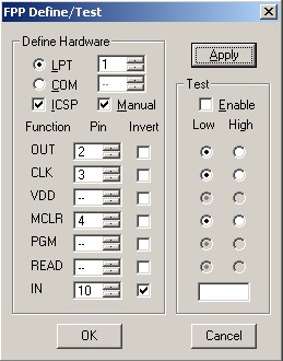
Modify your settings to match this screen, and then click on the "Apply" button. If you click "OK" before clicking on "Apply" all your settings will revert back to the previous settings. Click on the "OK" button on the "Define/Test" menu and then on the "Setup" menu. You should now be back at the main menu. Once you have this set up and running you can proceed to test read and program the PIC16F84A on the PIC-EL. Now you're ready for the Elmer 160 classes and on to developing your own code!
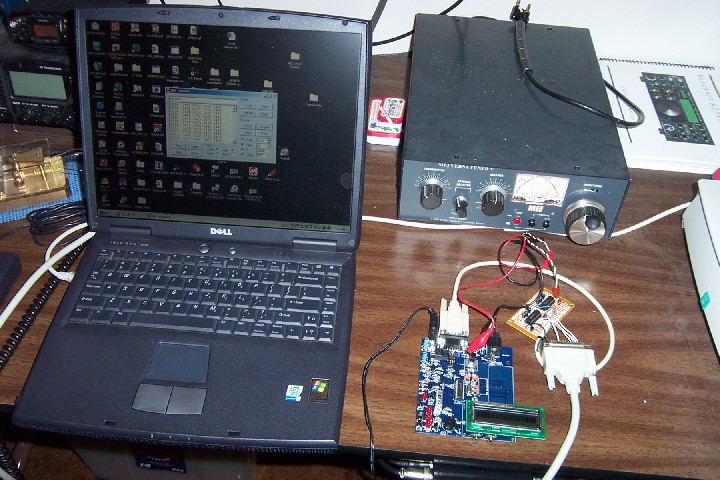
This is a pretty straight forward project, so I'm not going to design a PCB at this time. It only took me about an hour to hook it up point to point on the little Radio Shack PCB, and there are no SMD devices either. Here's a picture of my test setup:
Most notebooks these days are no longer coming with built in serial ports due to the wide spread use of USB technology, so I hope that some of you find this little project useful.
73's Trev