
K6ESE Mar Vista, CA Shack/Antenna Pics
April 15th 2004
Here is a collection of pictures that I shot of the new shack and antenna in Mar Vista (Los Angeles near Santa Monica), CA.
Here's a picture of yours truly sitting in front of the main computer in the center of the shack...long hair and all...
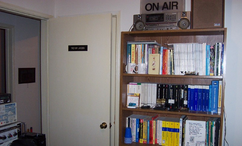
Here's what I'd be looking at at the back of the shack...

Vintage Operating Position: Collins R-390A and Johnson Ranger. Above the R-390A is a small audio amp and a frequency counter. to the right is my unamplified D-104. This station gets used on AM most of the time...
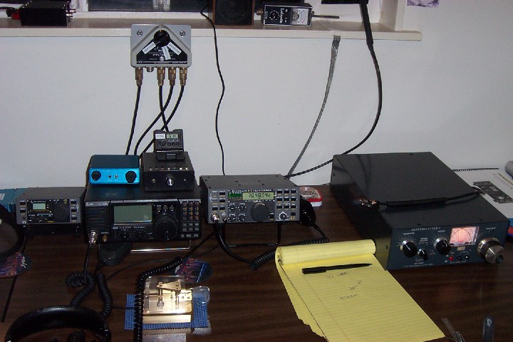
CW Operating Position: Rigs from left to right are an Elecraft K1, Icom 718, Elecraft K2 and a Small Wonder Labs DSW-40 on top of the Icom. Also on top of the Icom is my Jackson Harbor Press Island II Keyer that gets used mostly for contesting. It's an excellent keyer with lots of memories. The paddle is a Schurr Profi 2 supplied by Morse Express, and the big antenna tuner to the right is an MFJ Versa Tuner V - used for the Icom and Vintage station. The K1 and K2 internal tuners do a fine job on my EDZ antenna...
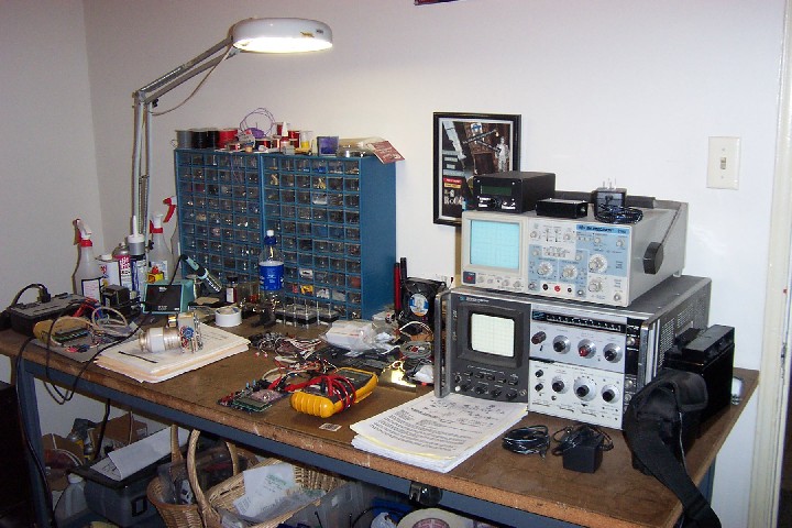
Here is the workbench to the right of the shack. Just acquired that HP Spectrum Analyzer last year. It sure comes in handy! The little box above the O-Scope to the left is my "Experimenter's DDS Signal Generator" and just to the right of that in yet a smaller box is an RF noise generator. The vacuum variable cap is part of a Magnetic Loop antenna project I'm working on.
...and now on to the antenna:
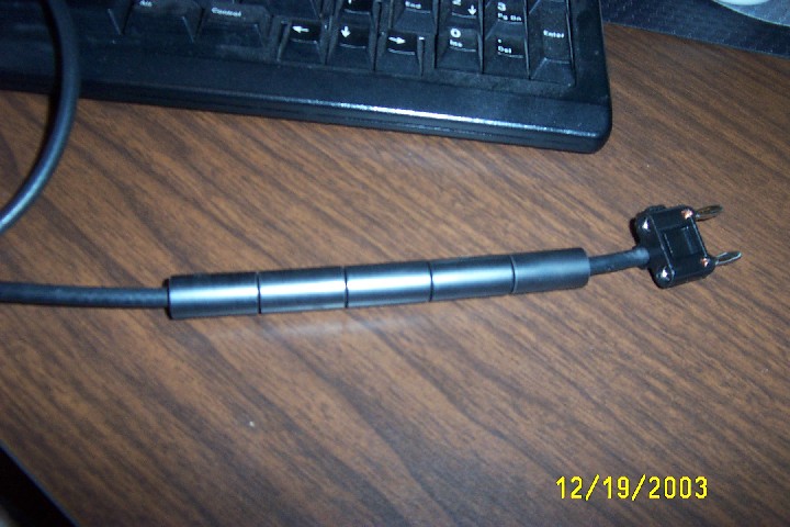
Here is how I transition the unbalanced coax to 450 ohm balanced line. The 5 ferrite beads form a 1:1 choke balun on the 3' piece of RG-8X. The beads are from Palomar Engineers. It's their BA-8 coax bead balun kit. It comes complete with heat shrink. I would guess that they are 77 mix beads, although 43 mix beads would probably work fine also. Thanks go to George W5YR for this idea. Note, this picture was taken during construction before I added heat shrink tubing. I built 2 of these. The first one for the K2 and K1 has a BNC connector on one end to feed the rig, and a dual banana plug on the other end to plug into the antenna. The other one is constructed identically, except that it has a PL-259 to go to the MFJ Versa Tuner V. Not shown is a 100K ohm 1/2 watt (1/4 watt would work fine, but that's all I had) resistor that is installed across the 2 pins of the banana plug to bleed off static buildup on the antenna. Thanks to Monty N5ESE for this idea! This arrangement works very well!

Here is how I make the transition from inside to outside and from unbalanced to balanced line. This is a section of Plexiglas that has been sealed into the horizontally sliding window here in the shack using gaffer's tape. I drilled holes for a dual banana jack so that I could connect and disconnect the antenna to the various feedlines. Outside, the 450 Ohm window line is soldered and heat shrunk to the banana jacks and sealed. The 3/4" tinned copper braid goes to 2 8' ground rods spaced about 6' apart just outside the window for the station ground.
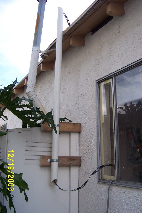
Here's a shot of the feedline outside of the shack. I cut a piece of 2" PVC Pipe to act as a guide to get the 450 ohm window line over the roof line and to keep it away from the house and other objects as much as possible.
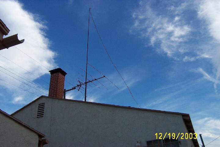
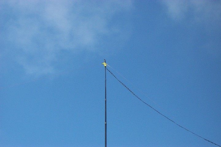
This was the most challenging aspect of the new QTH, how to hang the antenna. I thought about many different configurations of antennas, including verticals, loops etc, but always came back to the Center Fed Zepp, as it's always performed well for me. So the question was how to hang it. Since we have a fairly small yard, but the house is quite long and pointed roughly North-South, I decided to look for a non-metallic mast of at least 20' that would be sturdy enough for permanent use for at least a couple of years until I finally buy a place and a real tower! After doing a search on the internet I found just what I was looking for at the Winds of Atlantis kite shop on St. George Island, FL (highly recommended! Very nice people to do business with). The description on the sales receipt says it all: "22' Extra Heavy Duty Fiberglass Telescopic Pole". The real purpose of the pole is to hang a large wind sock from, but it works great for antennas too! It's been up since Early December and shows no sign of deterioration yet. The pole is 2" in diameter at the base to give you an idea of the size. Since we have a defunct TV antenna on the roof of the house in the perfect spot (couldn't have placed it better myself!) I used the TV mast to support the antenna mast with a few U clamps. Height at the Apex was measured at just shy of 40'.
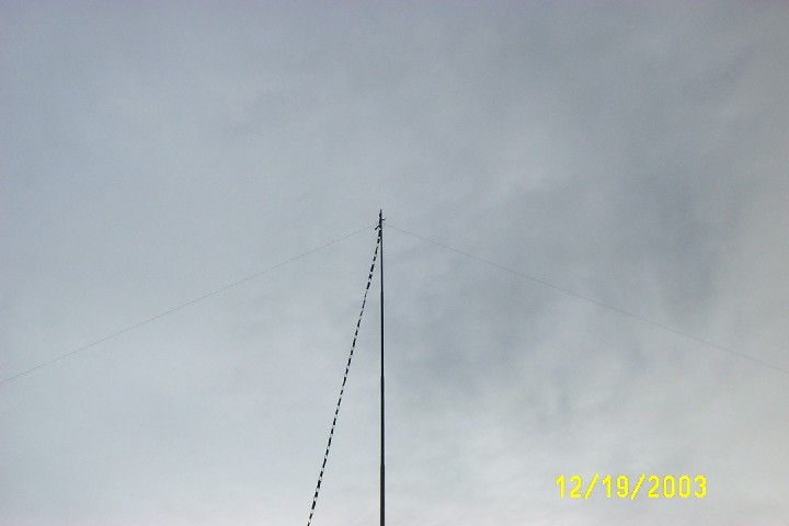
Here's a close-up of the finished antenna at the feedpoint. The antenna wire is #22 high strand count silver tinned Teflon insulated copper. I used this wire as I have a lot of it. There's nothing really special about it, except that the Teflon insulation seems to stand up to the Southern California sun very well. It was also light weight enough to not stress the mast. I thought about using heavier gauge solid copper, but this would be rather heavy in comparison. The center insulator/strain relief is made from a piece of 1/8" Plexiglas. The 450 Ohm Window Line is secured to the center insulator and soldered to the antenna wires. These joints also have heat shrink tubing and are sealed. The dimensions of the antenna wire are 44' per side making it 88' in total length. This forms an Extended Double Zepp on 20 Meters. The ends of the antenna slope down to either end of the house, and are about 10' off the ground. The antenna performs very well on 80 through 10 meters, and the best DX so far was R1ANF (South Shetland Islands, Antarctica) on 20 meters PSK31 with my K2 at 5 watts! This is also the antenna that I used in the 2003/2004 QRP-L 40 meter Winter Fox Hunts, and it did quite well.
ANTENNA UPDATE 04-30-2004
Last Friday 04-23-04 we had a very high wind storm that brought one leg of the Zepp down. The mast survived just fine. I was afraid that this may happen with the small gauge wire that I had used. So, rather than put the same wire back up I ordered some wire and parts (boy they have a lot of neat stuff!) from The Wireman. I ordered 200' of #14 copper clad steel (#502) for the new antenna (450 Lbs rating!), plus a "WA1FFL LadderLock" to replace the center insulator. This is a VERY nice center insulator! I usually just make one out of a piece of plastic, but the only stuff I have is too thin, so I thought I'd give the LadderLock a try. Boy I'm glad I did, this is a first rate center insulator. It really strain relieves the 450 Ohm Window Line very well. I also ordered a 1" marine grade pulley and 200' of 3/16" Dacron rope so that I could raise and lower the antenna without having to drop the mast. One thing that a few people mentioned to me is to be sure not to kink the wire in any way as it really weakens it. I was able to get the wire up in the air with no kinking. It wasn't easy though as this wire tends to want to do just that. It's very springy and wants to retain it's shape.
Here's a couple of shots:
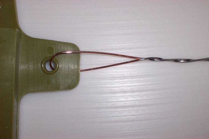
To make the loop in the antenna wire for the center insulator, I bent the wire smoothly around a 1" diameter rod. This gave the wire a nice kink free radius. Then twisted the wires together, but not to tightly, for about a 4" section. This was then soldered with silver (Kester #44 Flux - 62/36/02) solder. A similar technique was used to attach the ceramic egg insulators on the ends...
Here's a shot of the new feed point of the antenna with the LadderLock installed. I had been a bit concerned with the extra weight on the mast, but it didn't bend an inch! Very sturdy indeed!
With the new antenna wire installed, I went into the shack and fired up the K2. The rig still tunes the antenna just fine, so looks like everything is working. Bands were not in great shape tonight, lots of noise, but I did have a quick QSO with Vance WA7ROI in Boise, ID on 40 Meters, so guess it's working OK...
That's all for now...dit dit
73's Trev